


Redundant Links 2-15
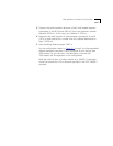
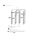
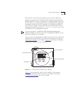
To set link redundancy between two 24-Port modules, connect two
links to two ports on the 50-pin cables between the modules. You
need to use a crossover adapter between each link because the links
are designed to be connected to a LAN card in an end node, not to
other module ports. Use the SET PORT {slot.port} MODE REDUNDANT
{slot.port} network management command to specify which port is the
primary link and which is the backup link. For example, if you set up a
redundant link with the following:
SET PORT 7.4 MODE REDUNDANT 8.9
Port 4 in slot 7 becomes the primary link and port 9 in slot 8 becomes
the backup link.
CAUTION: Redundancy on the 24-Port module is a management
module software function. Consequently, a network loop could occur
if the module is set to redundant mode and it is powered down and
then brought back up without a management module in the hub.
Once redundancy is configured, a switchover to the backup link occurs
under two conditions: a link failure or a port partition. Once the
switchover occurs and the backup link becomes operational, a
switchover back to the primary link happens automatically once the
problem is resolved.
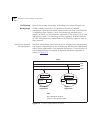
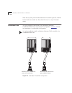
Although it is possible to configure redundancy between two ports on
a single module, we recommend that you configure redundancy
between two ports on two different modules. This provides more
protection if, for example, one of the modules becomes inoperative.
Refer to the Distributed Management Module User Guide for
information on setting redundancy between 24-Port module ports.