


3-22 INSTALLING AND OPERATING THE MODULE
Monitoring the
Front Panel
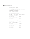
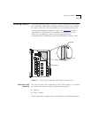
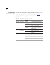
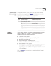
The LEDs on the front panel of the 24-Port module allow you to
monitor the status of each port. The 24-Port module has a pair of
Activity and Status LEDs for each port. Figure 3-8
shows the location of
the LEDs. Each LED indicates the state of a port as described in
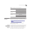
Table 3-3
.
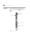
Figure 3-8 24-Port Module Faceplate
ACTIVITY
STATUS
24
23
22
21
20
19
18
13
17
16
15
14
12
11
10
9
8
7
6
5
4
3
2
1
STATUS
MODULE
Module Status LED
Port Status LEDs
50-pin connector (ports 1 - 12)
50-pin connector (ports 13 - 24)
Port Activity LEDs