


3-10 INSTALLING AND OPERATING THE MODULE
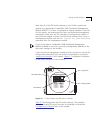
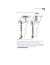
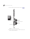
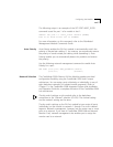
9 Secure the cables to the module connectors as shown in Figure 3-4.
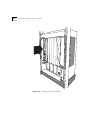
Figure 3-4 24-Port Module Cable Connection
10 Attach the other ends of the cables to a 10BASE-T transceiver, patch
panel, or a 10BASE-T adapter card.
180 50-pin cable connectors
ACTIVITY
STATUS
24
23
22
21
20
19
18
13
17
16
15
14
12
11
10
9
8
7
6
5
4
3
2
1
STATUS
MODULE
50-pin connector
3
2
1
2
1
3
4
3
2
1
2
1
3
4
24
23
22
21
20
19
18
13
17
16
15
14
12
11
10
9
8
7
6
5
4
3
2
1
24
23
22
21
20
19
18
13
17
16
15
14
12
11
10
9
8
7
6
5
4
3
2
1
o