


Spanning Tree Algorithm Configuration
3-149
3
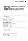
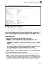
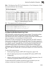
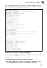
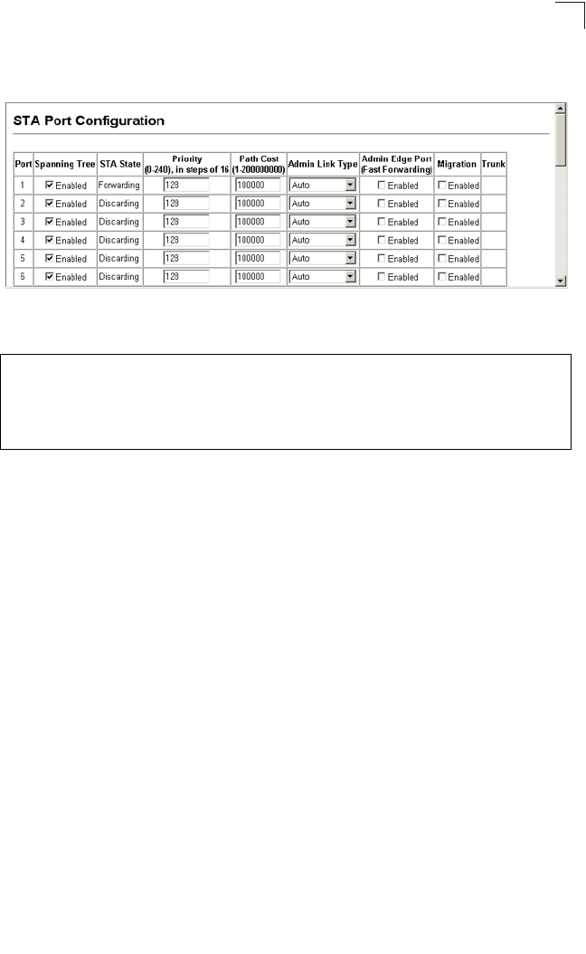
Web – Click Spanning Tree, STA, Port Configuration or Trunk Configuration. Modify
the required attributes, then click Apply.
Figure 3-90 Configuring Spanning Tree per Port
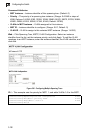
CLI – This example sets STA attributes for port 7.
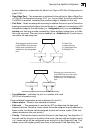
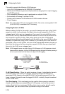
Configuring Multiple Spanning Trees
MSTP generates a unique spanning tree for each instance. This provides multiple
pathways across the network, thereby balancing the traffic load, preventing
wide-scale disruption when a bridge node in a single instance fails, and allowing for
faster convergence of a new topology for the failed instance.
By default all VLANs are assigned to the Internal Spanning Tree (MST Instance 0)
that connects all bridges and LANs within the MST region. This switch supports up
to 9 instances. You should try to group VLANs which cover the same general area of
your network. However, remember that you must configure all bridges within the
same MSTI Region (page 3-133) with the same set of instances, and the same
instance (on each bridge) with the same set of VLANs. Also, note that RSTP treats
each MSTI region as a single node, connecting all regions to the Common Spanning
Tree.
To use multiple spanning trees:
1. Set the spanning tree type to MSTP (STA Configuration, page 3-130).
2. Enter the spanning tree priority for the selected MST instance (MSTP VLAN
Configuration).
3. Add the VLANs that will share this MSTI (MSTP VLAN Configuration). Note: All
VLANs are automatically added to the IST (Instance 0).
To ensure that the MSTI maintains connectivity across the network, you must
configure a related set of bridges with the same MSTI settings.
Console(config)#interface ethernet 1/7 4-166
Console(config-if)#spanning-tree port-priority 0 4-228
Console(config-if)#spanning-tree cost 50 4-227
Console(config-if)#spanning-tree link-type auto 4-231
Console(config-if)#no spanning-tree edge-port 4-229
Console(config-if)#