


19
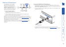
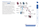
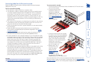
3 Connect the other end of the cascade
link cable to one of the CATx USER PORTS
sockets on the rear panel of the lower
unit. Due to the way in which ports
within a link group are dynamically
allocated, it is not usually important
exactly which user port is
connected to each computer
port of the upper unit.
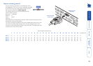
4 Repeat steps 2 and 3
for each of the links
within the group,
adhering to the
Group numbering
diagram for
the correct link group
boundaries on the COMPUTER
CONNECTIONS ports of the upper switch.
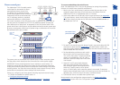
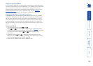
Once the AdderView CATx units and computers have been connected, you can
edit their names to make it much easier to locate them. See the To create/edit
computer names section in the Configuration chapter for more details.
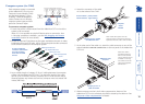
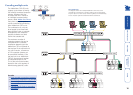
Connecting AdderView CATx units in cascade
Please consider the following when making cascade connections between
AdderView CATx units.
Tips for successful cascading
• The maximum number of levels for a cascade is three.
• The maximum number of computer systems that can be controlled within
a cascade installation depends upon the AdderView CATx unit placed at
the top level. If the top level unit is a non-IP version, a maximum of 512
computer systems can be controlled. However, if the top level unit is an
AdderView CATx IP, the maximum number of computers drops to 128. This
is due to the extra burden placed on the unit’s memory of administering
global (IP) users.
• The number of links between units determines the number of users that can
simultaneously access the computers situated further down the tree. Link
groups of one and two links should be discouraged.
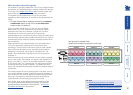
• Ensure that cascade links (within a group) between units are approximately
the same length.
• Triple and quad link groups may be mixed on one unit providing the
links lie within the appropriate port boundaries designated in the Group
numbering diagram.
• AdderView CATx IP models should only be used at the top level of the
cascade tree because they have only two CATx USER PORTS sockets.
• For each cascade link, use a standard category 5, 5e or 6 twisted-pair cable,
terminated at each end with an RJ45 connector. There must be no crossover
connections within the cable, i.e. do not use patch cables. The cascade link
cables can be up to 50m (160 feet) in length. However, remember that
the overall length between any remote user (via an X100 extender) and
any computer (via a CAM) must not exceed 300m (980 feet) - that figure
includes the cascade link cables. Ensure that each of the links within a
cascade group all conform to the same length.
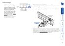
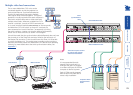
• The procedure given opposite may be carried out in any order but for clarity
the instruction will begin at the higher level AdderView CATx unit (here
called the upper unit), i.e. the one that is being fed into by a unit at the
cascade level below (here called the lower unit). The procedure remains the
same regardless of exactly which cascade levels are being connected. The
basic rule is that each link is made by connecting a COMPUTER CONNECTIONS
port of the upper switch to a CATx USER PORTS of the lower switch.
To connect units in cascade
1 Ensure that power is disconnected from the AdderView CATx and all other
units to be connected.
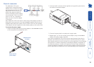
2 Connect one end of each
cascade link cable to an
appropriate
COMPUTER
CONNECTIONS port on the rear
panel of the upper unit. Refer
to the Group numbering
diagram for the correct link
group boundaries.
See also
• Testing specific links to cascaded computers