


94 Installation and User’s Guide
3 Verifying System Functionality
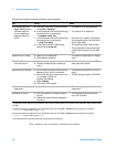
Understanding the System Functional Verification Test
The system functional verification test is a standard IC- CAP measurement
and simulation procedure. The system performs DC and S- parameter
extraction, optimization, and simulation using a fixed 10 dB attenuator as
the device under test (DUT).
The procedure provided in “Performing the System Functional Verification
Test” confirms:
• the IC- CAP software can communicate with and control the system
instrumentation via GPIB (through the LAN/GPIB gateway, if so
configured)
• the system can make measurements and display the results
• the IC- CAP software can simulate data
• the IC- CAP software can converge the simulated data with the
extracted (measured) data
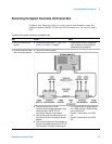
The system applies forward and reverse current to the attenuator and
monitors voltage at the attenuator’s input and output. IC- CAP then uses
the measured data to model the device- intrinsic resistances and
transmission line delay.
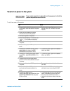
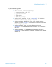
Required Tools
• Agilent 85225F performance modeling system
• A system controller
*
• Agilent 85190A IC- CAP software
• Test port cables
• Agilent 8490D 10 dB fixed RF attenuator
†
• BNC tee (2)
‡
• Agilent 11900A, 2.4 mm male- to- male adapter
• Agilent 11900B, 2.4 mm female- to- female adapter
• Agilent 11900C, 2.4 mm female- to- male adapter
• Agilent 85056A 2.4 mm precision calibration kit, or
• Agilent 85056D 2.4 mm economy calibration kit
* For requirements, see “The System Controller" on page 59.
† These components are supplied as part of the system.
‡ For CV subsystem verification only