


104 007-5510-002
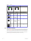
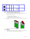
5.4.2 Internal Indicators
Note In some components, the failure LED is internal to the enclosure and visible only when the cover is open.
The Internal LED indicators are explained in Table 5–4.
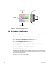
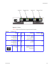
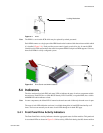
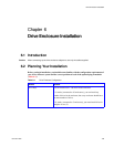
5.4.3 Rear of Enclosure Activity Indicators
The PCMs and the I/O Modules are located on the rear of the enclosures. The LEDs on the rear of the
enclosure are explained in Table 5–5.
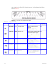
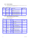
Table 5–4 INTERNAL LED Indicators
Description Location Color Normal Behavior Enclosure Audible
Alarm
DEM DC DEM internal to
enclosure
GREEN ON-1.2VDC regulator circuit correctly
functioning
OFF- faulty 2.1VDC regulator circuit
Off
DEM ID DEM internal to
enclosure
BLUE ON-receiving SES identity command
OFF-NOT receiving SES identity command
Off
HDD ID HDD internal to
enclosure
BLUE ON-receiving SES identity command
OFF-NOT receiving SES identity command
Off
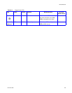
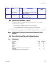
Table 5–5 LEDs on the Rear of the Enclosure
Description Location COLOR Normal Behavior Enclosure Audible
Alarm
PCM DC ok PCM
rear of enclosure
GREEN ON-DC output of PCM within tolerances.
OFF-failed PCM
Off
PCM AC ok PCM
rear of enclosure
GREEN ON-AC input to PCM within tolerances.
OFF-failed PCM
Off
PCM Fault PCM
rear of enclosure
AMBER ON - PCM fault detected
OFF - no detected PCM faults.
Off
PCM ID PCM
rear of enclosure
BLUE ON-receiving SES identity command
OFF-NOT receiving SES identity command
Off
I/O Module ok I/O Module
rear of enclosure
GREEN ON-properly booted and functioning
correctly.
OFF-I/O Module internal fault
Off
I/O Fault I/O Module
rear of enclosure
AMBER ON - I/O module fault detected
OFF - no detected I/O module faults.
Off
I/O Module ID I/O Module
rear of enclosure
BLUE ON-receiving SES identity command
OFF-NOT receiving SES identity command
Off