


6 007-5510-002
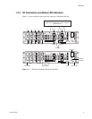
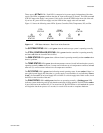
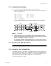
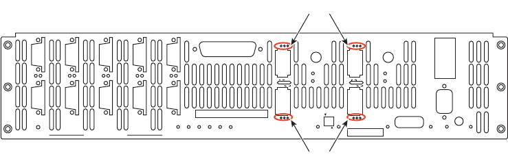
Figure 1–4 Host Port LEDs
The four HOST ports are used for IB or FC-8 host connections. You can connect your host servers IB
HCA port(s) or FC HCA port(s)directly to these ports. Additionally, you can connect these ports to your
IB or FC switches and hubs.
The
IB LEDs (the Infiniband LEDs) located between the host ports, when solid green, indicate that
there is physical connectivity with the host; when steady amber, they indicate that the subnet manager
is communicating with the host.
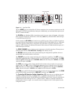
On FC-8 models, the
FC LEDs are located next to each FC host port. There are 3 LEDs for each host
port, which indicate if the connection is running at 8 GB (left LED), 4 GB (middle LED), or 2 GB (right
LED). The respective LED will be a solid green to show that there is a physical connection. If the
respective LED is flashing, this indicates data transfer. If the connector is taken from the host port, all 3
LEDs for that port will flash.
The
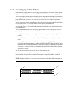
DISK CHANNEL ports ( jackscrew style connectors) are for disk connections. The ten ports are
labeled by data channels (ABCDEFGHPS). Flashing LEDs indicate activity.
The
RS-232 connector provides local system monitoring and configuration capabilities and uses a
standard DB-9 null modem female-to-male cable.
The
TELNET port provides remote monitoring and configuration capabilities. The ACT (Activity)
LED flashes green when there is Ethernet activity. It is unlit when there is no Ethernet link. The
LINK
LED turns green when the link speed is 1000MB/s, amber when the link speed is 100MB/s, and is unlit
when the link speed is 10 MB/s.
The
LINK port is used to connect single controller units in order to form a couplet via a cross-over
Ethernet cable. The
ACT (Activity) LED flashes green when there is Ethernet activity. The LED is
unlit when there is no Ethernet link. The
LINK LED turns green when the link speed is 1000MB/s,
amber when the link speed is 100MB/s, and is unlit when the link speed is 10 MB/s.
The
COM port is an RS-232 Interface that uses an RJ-45 cable and connects controller units. The COM
port has two(2) LEDs associated with it:
HDD ACT (Activity) and LINK ACT.
The
Controller ID Selection Switch (labeled as 1/2) allows the user to configure the units
as Unit 1 or Unit 2. Each unit has an activity LED. It is green for the selected unit. The switch is
comprised of two DIP switches. The first DIP switch (indicated by the 1/2 label ) is used to select the unit
configuration. Flip the switch up for Unit 1---down for Unit 2. When two controller controllers are
paired together to form a couplet, one controller must be configured as unit 1 and its partner must be
configured as unit 2.
P
S
PS
G
H
GH
A
B
AB
E
F
EF
C
D
CD
DISK CHANNELS
AC
FAIL
SYSTEM
STATUS
CTRL
STATUS
TEMP
STATUS
DISK
STATUS
DC
STATUS
FAN
STATUS
TEST
STATUS
ACT
HOST 1/2
CLI
HOST 1
HOST 2
1
2
STATUS
ACT
HOST 3/4
CLI
HOST 3
HOST 4
3
4
1/2
TEST
PLACE PIN HERE
LINK
ACT
MUTE
AC
FAIL
ACT
LINK
ACT
LINK
TELNET
ALARM
SILENCE
CLI
COM
LINK
Host port LEDs
Host port LEDs