


Controller Installation
007-5510-002 13
2.2.3 Connecting the Controller
To set up the disk enclosures and connect them to the controller, do the following.
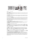
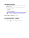
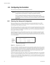
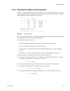
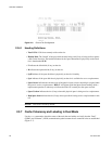
1. There are 10 disk channels on the controller. They correspond with disk ports. The disk ports are
labeled as follows (Figure 2–1
):
DISK A = Channel A DISK B = Channel B
DISK C = Channel C DISK D = Channel D
DISK E = Channel E DISK F = Channel F
DISK G = Channel G DISK H = Channel H
DISK P = Channel P (parity)
DISK S = Channel S (spare)
Using the 10 copper SAS cables provided, connect these disk ports to your ten disk channels.
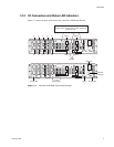
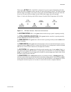
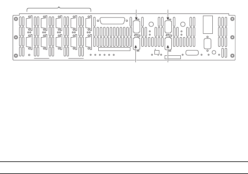
Figure 2–1 I/O Connectors
2.
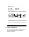
Each controller supports up to four host connections. You may connect more than four client
systems to the controller using switches and you can restrict user access to the LUNs (as described
in Section 2.3 "Configuring the Controller" of this guide).
The Host ports are numbered 1 through 4 as shown in Figure 2–1. Connect your host system(s) or
switches to these ports. For FC-8 models, ensure that the latches on the transceivers are engaged.
2.2.4 Selecting SAS- ID for Your Drives
NOTE :
The controller uses a select ID of 1.
2.2.5 Laying Out your Storage Drives
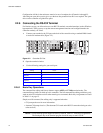
Tiers, or RAID groups, are the basic building blocks of the controller. A tier can be catalogued as 8+1
or 8+2. In 8+1 mode, a tier contains 10 drives—eight (8) data drives (Channels A through H), one parity
drive (Channel P), and one optional spare drive (Channel S). In 8+2 mode, a tier contains 10 drives—
eight (8) data drives (Channels A through H) and two parity drives (Channel P and S).
The controller can manage up to 120 tiers.
P
S
PS
G
H
GH
A
B
AB
E
F
EF
C
D
CD
DISK CHANNELS
AC
FAIL
SYSTEM
STATUS
CTRL
STATUS
TEMP
STATUS
DISK
STATUS
DC
STATUS
FAN
STATUS
TEST
STATUS
ACT
HOST 1/2
CLI
HOST 1
HOST 2
1
2
STATUS
ACT
HOST 3/4
CLI
HOST 3
HOST 4
3
4
1/2
TEST
PLACE PIN HERE
LINK
ACT
MUTE
AC
FAIL
ACT
LINK
ACT
LINK
TELNET
ALARM
SILENCE
CLI
COM
LINK
Host port 3Host port 1
Host port 4Host port 2
Disk ports