


110 007-5510-002
6.2.1 Enclosure Bay Numbering Convention
Warning Operation of the Enclosure with ANY of the plug-in modules missing from the rear of the
enclosure will disrupt the airflow and the drives will not receive sufficient cooling. It is
ESSENTIAL that all (rear) apertures are filled before operating the unit.
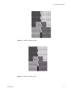
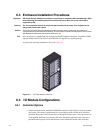
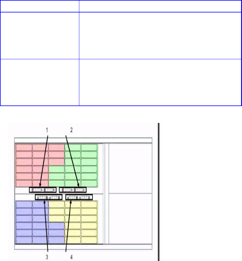
The drive enclosure subsystem is housed in a 60-drive bay enclosure, arranged in four (4) groups. Each
group comprises two banks of 15 bays, that is, (as viewed from the front): 12 bays across the enclosure
by 5 bays deep. There are two numbering schemes: 1x60 and 2x30. The drive bays are numbered in
accordance with the tables shown in Figure 6–2 and Figure 6–3, when viewed from above.
Note Drive 61 is optional drive.
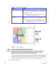
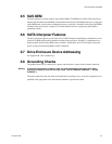
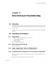
Power Cooling Modules (PCM) Two (2) PCMs must be fitted. Full power and cooling redundancy
is provided while a faulty module is replaced. Install the PCMs in
lower rear bays A and B.
Note: Rear bays are numbered from A and B starting from the
left when viewed from the back.
I/O Module One or two I/O modules should be Installed in the upper rear bays
A & B.
Note: If only one module is installed, it should be fitted in
Module Location A and a blank plate must be fitted
over the unused bay.
Figure 6–1 DEM Pair Locations
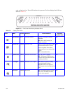
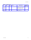
Table 6–1 Drive Enclosure Configuration
Module Location
Bay B
I/O
Bay A
I/O