


4 007-5510-002
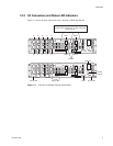
1.2.1 Power Supply and Fan Modules
Each controller is equipped with two (2) power supply modules and one (1) fan module. The PSU (power
supply unit) voltage operating ranges are nominally 110V to 230V AC, and are autoranging.
The two Power Supply modules provide redundant power. If one module fails, the other will maintain the
power supply and cooling while you replace the faulty module. The faulty module will still be providing
proper air flow for the system so do not remove it until a new module is available for replacement.
The two power supply modules are installed in the lower left and right slots at the front of the unit, behind
the cover panel
(Figure 1–1). Each PSU module is held in place by one thumbscrew.
The fan module (Figure 1–1) is installed in the front top slot, behind the cover panel, and held in place
by two thumbscrews.
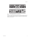
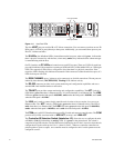
The two LEDs mounted on the front of the power supply module (located on the right and left of the
power supply handle) indicate the status of the PSU:
• Both LEDs will be lit green when the supply is active and the output is within operating limits with
no faults.
• The left LED indicates the status of the AC input. The LED is lit green as long as the AC input is
present.
• The right LED indicates the status of the DC output of the power supply. The LED is lit green when
the supply is enabled and the outputs are withing specification. The LED will be off when AC input
is not present, the outputs are disabled (after a SHUTDOWN command), or the outputs are not within
specification. A cooling fan failure will not turn this LED off unless the failure results in a thermal
shutdown of the supply.
The AC switch for each supply is located on the rear of the controller unit.
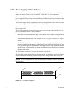
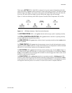
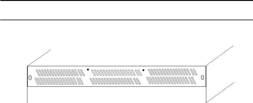
The fan module contains multiple fans for cooling the controller. It is the primary source of cooling and
must be installed at all times during operation (except when it is being replaced due to a faulty fan).
NOTE :
For more information on fan status, see the description of the Status LEDs on rear panel in
the next section.
Figure 1–2 Fan Module (front panel)