Introduction
007-5510-002 7
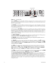
There are two AC Fail LEDs. Each LED is connected to its power supply independent of the other
supply. The LEDs are green to indicate that the AC input to the supply is present. The LEDs turn red
if the AC input to the supply is not present. If this occurs, check the LEDs on the front side of the unit.
If you lose AC power from one supply cord, the LED for that supply outlet will turn red.
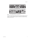
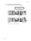
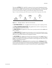
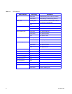
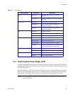
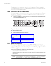
Figure 1–5 shows the following status LEDs: System, Controller, Disk, Temperature, DC, and Fan.
Figure 1–5 LED Status Indicators - Rear Panel of the Controller
The SYSTEM STATUS LED is solid green when the entire storage system is operating normally.
The
CTRL (CONTROLLER) STATUS LED is green when the controller is operating normally
and turns red when the controller unit is failed.
The
DISK STATUS LED is green when a disk enclosure is operating normally and turns amber when
there is a problem.
The
TEMP STATUS LED is green when the temperature sensors (6 total) indicate that the system is
operating normally, amber when one (1) temp sensor indicates an over-temperature condition, and red
when two (2) or more sensors indicate an over-temperature condition.
The
DC STATUS LED is green when indicating normal operating status. It turns amber if there is a
non-critical power Supply DC fault (that is, a power supply is not installed or is not indicating “Power
Good”). It turns red if an on-board supply fails or if there is a critical supply fault. If this occurs, check
the LEDs on the front side of the unit.
The
FAN STATUS LED is solid green when fans are operating normally. A flashing green LED
indicates system monitoring activity such that the monitoring is being updated. The LED flashes amber
if one of the fans in the module fails. If 2 or more fans fail, the LED flashes a solid red and the system
will begin the shut down process at 5 seconds, for a total of 30 seconds to complete shutdown.
CTRL
FAN
SYSTEM
DC
TEMP
STATUS
STATUS
STATUS
STATUS
STATUS
STATUS
DISK


