DCS-200 • User’s Guide 21
2. Hardware Orientation
DCS-200 Front Panel
aáëéä~ó=pÉÅíáçå
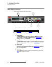
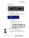
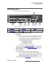
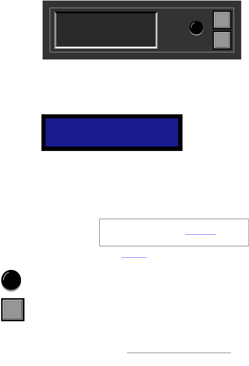
The figure below illustrates the Display Section:
Figure 2-2. Display Section with sample Status Menu
Descriptions of each button and control are provided below:
• The Menu Display is a 4-line x 20-character Vacuum Fluorescent Display (VFD)
that shows all DCS-200 menus and sub-menus. Brightness is adjustable. The
following illustration shows a typical DCS-200 menu.
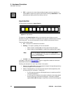
Figure 2-3. Sample Setup Menu Display
For all setup menus, please note:
~ The top line names the current menu, in all capital letters.
~ The navigation cursor (>) in the left-hand column indicates the current
line on which action can be taken.
~ The double arrow (>>) indicates that a sub-menu is available.
In Chapter 4, refer to the “Menu Tree
” section on page 38 for additional details on
the system’s menu tree.
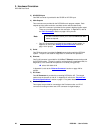
• ADJUST — use the Adjust Knob to scroll through all system menus.
~ Turn the knob counter-clockwise (CCW) to scroll down.
~ Turn the knob clockwise (CW) to scroll up.
• SEL — press to enter the setup menu tree (from the Status Menu), to enter a
sub-menu, change a parameter, accept a parameter, or to answer “Yes” to certain
menu queries.
SETUP MENU
> Trans Time 1.0
Output >>
Preview >>
Adjust
SEL
ESC
PROGRAM:
NEXT:
RGB
1024x768 @59.94
SDI
NTSC (480i)
Note
The Status Menu layout is different from the “setup” menu
display. In Chapter 4, refer to the “Status Menu
” section on
page 44 for details.
SEL


