


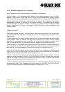
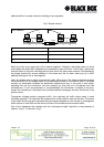
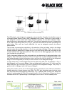
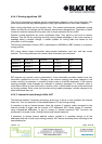
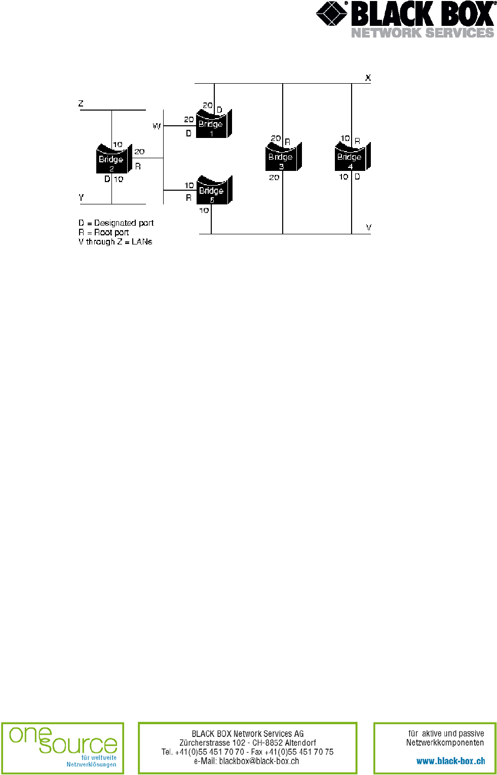
Fig. 4 Network before running STA
The STA calls for each bridge to be assigned a unique identifier. Typically, this identifier is one of
the bridge's Media Access Control (MAC) addresses plus a priority. Each port in every bridge is
also assigned a unique (within that bridge) identifier (typically, its own MAC address). Finally,
each bridge port is associated with a path cost. The path cost represents the cost of transmitting
a unit onto a LAN through that port. In Fig. 4, path costs are noted on the lines emanating from
each bridge. Path costs are usually defaulted, but can be assigned manually by network
administrators.
The first step in spanning-tree calculation is the selection of the root bridge, which is the bridge
with the lowest value bridge identifier. In Fig. 4, the root bridge is Bridge 1. Next, the root port on
all other bridges is determined. A bridge root port is the port through which the root bridge can be
reached with the least aggregate path cost. This value (i.e. the least aggregate path cost to the
root) is called the root path cost.
Finally, designated bridges and their designated ports are determined. A designated bridge is the
bridge on each LAN that provides the minimum root path cost. A LAN's designated bridge is the
only bridge allowed to forward information units to and from the LAN for which it is the designated
bridge. A LAN's designated port is the port that connects it to the designated bridge.
In some cases, two or more bridges can have the same root path cost. For example, in Fig. 4,
both Bridges 4 and 5 can reach Bridge 1 (the root bridge) with a path cost of 10. In this case, the
bridge identifiers are used again, this time to determine the designated bridges. The priority is
given to LAN V of Bridge 4 over LAN V port of Bridge 5.
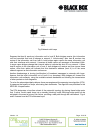
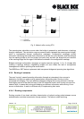
Using this process, all but one of the bridges directly connected to each LAN are eliminated,
thereby removing all loops between two LANs. The STA also eliminates loops involving more
than two LANs, while still preserving connectivity. Fig. 5 “Network after running STA” shows the
results of implementing the STA to the network shown in Fig. 4. Comparison of these two figures
illustrates that the STA placed Bridge 3 and Bridge 5 ports to LAN V into the standby mode.
Version: 1.0 Page. 24 of 95