


3
Chapter1:Valet
/
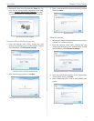
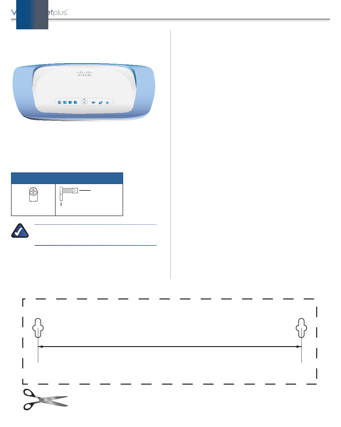
HorizontalPlacement
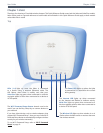
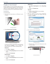
TheValethasfourrubberfeetonitsbottompanel.Place
theValetonalevelsurfacenearanelectricaloutlet.
Wall-MountingPlacement
TheValethastwowall-mountslotsonitsbottompanel.
Thedistancebetweentheslotsis152mm.
TwoscrewsareneededtomounttheValet.
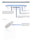
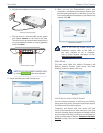
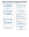
Suggested Mounting Hardware
2.5-3.0mm
4-5mm 1-1.5mm
NOTE: Cisco is not responsible for damages
incurredbyunsecuredwall-mountinghardware.
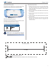
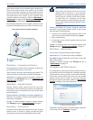
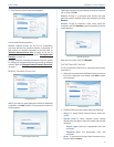
Wall-MountingTemplate
Printthispageat100%size.
Cutalongthedottedline,andplaceonthewalltodrillprecisespacing.
152 mm
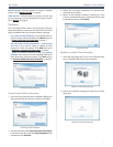
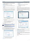
Followtheseinstructions:
1. DeterminewhereyouwanttomounttheValet.Make
sure that the wall you use is smooth, flat, dry, and
sturdy.Alsomakesurethelocationiswithinreachof
anelectricaloutlet.
2. Drilltwoholesintothewall.Makesuretheholesare
152mmapart.
3. Inserta screwintoeach holeandleave3 mmofits
headexposed.
4. PositiontheValetso thewall-mountslots lineupwith
thetwoscrews.
5. Placethewall-mountslotsoverthescrewsandslide
the Valet down until the screws fit snugly into the
wall-mountslots.