


1-7
Cisco Physical Access Gateway User Guide
OL-20932-02
Chapter 1 Overview
Optional Expansion Modules
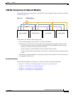
CAN Bus Connections for Optional Modules
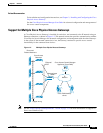
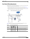
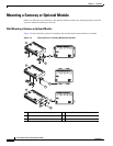
The optional modules are connected to a Cisco Physical Access Gateway using a CAN bus connection,
as shown in Figure 1-5.
Figure 1-5 CAN Bus Wiring
The CAN bus must adhere to the following rules:
• The maximum length for the CAN bus is 1320 feet (400 Metres).
• The last device in a CAN bus must be terminated by setting the CAN terminator switch to ON.
–
The CAN terminator switch in included on the Reader, Input and Output modules only (the
Gateway is always the first device in the CAN bus).
–
Set the terminator switch to OFF for all other modules in the CAN bus.
–
For the location of the CAN terminator on each device, see the physical port description for that
device.
• The Gateway and Reader modules are connected using the CAN1 interface. The CAN2 interface is
not supported in this release.
Related Documentation
See the following chapters for instructions to install the modules and related equipment:
• Chapter 2, “Installing and Configuring the Cisco Physical Access Gateway”
• Chapter 3, “Connecting a Cisco Reader Module”
• Chapter 4, “Connecting a Cisco Input Module”
• Chapter 5, “Connecting a Cisco Output Module”
271589
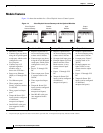
Gateway Module Reader Module Input Module Output Module
CAN+
CAN-
Sheild