


4-7
Cisco Physical Access Gateway User Guide
OL-20932-02
Chapter 4 Connecting a Cisco Input Module
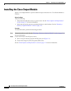
Installing the Cisco Input Module
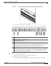
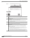
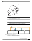
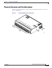
Figure 4-6 CAN Connections: Input and Output Modules
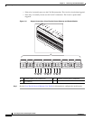
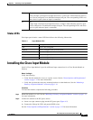
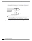
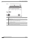
Figure 4-7 CAN Bus Wiring
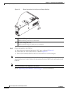
Step 4
Connect input devices to the module:
a. Insert two-pin connector plugs into the input ports.
1 CAN+
Connects to the positive terminal of the CAN bus.
2 CAN-
Connects to the negative terminal of the CAN bus.
3 Shield
Connects to GND and/or Shield.
3 CAN Terminator
Turn the terminator ON if the device is the last device in a CAN wiring bus.
271598
2
3
1
4
271589
Gateway Module Reader Module Input Module Output Module
CAN+
CAN-
Sheild