


4-6
Cisco Physical Access Gateway User Guide
OL-20932-02
Chapter 4 Connecting a Cisco Input Module
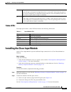
Installing the Cisco Input Module
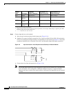
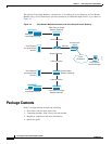
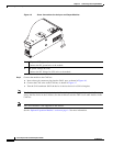
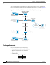
Figure 4-5 Power Connections for the Input and Output Modules
Step 3
Connect the module to the CAN bus:
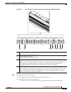
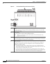
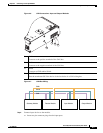
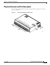
a. Insert a three-pin connector plug into the CAN1 port, as shown in Figure 4-6.
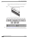
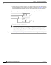
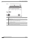
b. Connect the CAN wires to the CAN bus, as shown in Figure 4-7
c. Turn the CAN terminator ON if the device is the last device in a CAN wiring bus.
Note The CAN terminator switch in included on the Reader, Input and Output modules only (the Gateway is
always the first device in the CAN bus). Set the terminator switch to OFF for all other modules in the
CAN bus.
Note The CAN2 interface is not supported in this release.
See the “Optional Expansion Modules” section on page 1-5 for more information.
1 DC power GND (ground)
Connects the DC ground wire to the module.
2 DC power Voltage In (VIN)
Connects the DC Voltage In (VIN) wire to the module.
271599
1
2