


3-11
Cisco Physical Access Gateway User Guide
OL-20932-02
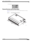
Chapter 3 Connecting a Cisco Reader Module
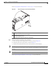
Installing the Cisco Reader Module
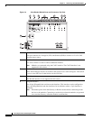
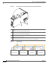
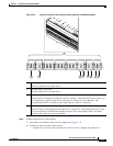
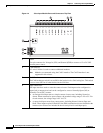
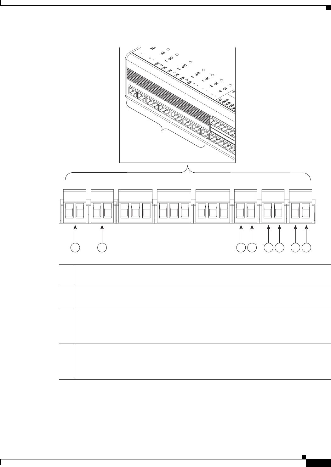
Figure 3-10 Input Connections: Cisco Physical Access Gateway and Reader Module
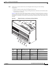
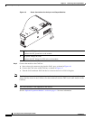
Step 6
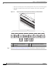
Connect output devices to the module:
a. Insert three-pin connector plugs into the output ports (Figure 3-11).
b. Connect the wires from the output devices.
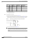
–
Common (C) is always used, and either NC or NO is used to complete the connection.
1 Positive Input Connections
Positive connection to an Input device.
2 Ground Input Connections
Ground connection to an Input device.
3 TM
Tamper input: an unsupervised input that raises a “tamper” alarm when the circuit is open. Can
be configured as a general input device using the Cisco Physical Access Manager. The
corresponding LED is red when circuit is open (when no input is connected).
4 PF
Power fail input: an unsupervised input that raises a “power fail” alarm when the circuit is open.
Can be configured as an additional unsupervised port. The corresponding LED is red when
circuit is open (when no input is connected).
271592
3 4 1 21 21 2