


2-10
Cisco Physical Access Gateway User Guide
OL-20932-02
Chapter 2 Installing and Configuring the Cisco Physical Access Gateway
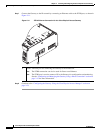
Installing the Cisco Physical Access Gateway
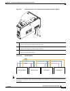
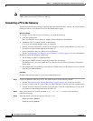
Step 4 Connect input devices to the Gateway:
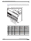
a. Insert two-pin connector plugs into the input ports (see Figure 2-7).
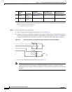
b. (Optional, for supervised input connections only). Install two End-Of-Line (EOL) 1K termination
resistors in each supervised input interface (one terminator in each connector). Figure 2-6 shows the
terminator installation for a Normally Closed (NC) and Normally Open (NO) input connection.
Figure 2-6 Input Connections: Cisco Physical Access Gateway and Reader Module
c.
Connect the wires from the input devices (see Figure 2-7).
Note Each of the input connections can be configured as supervised or unsupervised. The tamper and
power fail inputs can be configured as additional unsupervised ports. A supervised input
supports four states: normal, alarm, open and short. An unsupervised input indicates only normal
or alarm.
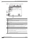
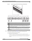
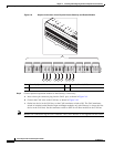
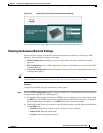
9 HCRD Hold
Control
HCRD (blue) ---------- D1/CLCK (white)
10 CP Card
Present
CP (purple) ---------- D0 (green)
1. Wire colors are shown in parentheses.
2. Outputs show the LED color and reader wire color (in parentheses). For example, “GRN (orange)” supports a green LED.
Attach the orange wire from the reader device.
3. ---------- means the wire slot is not used.
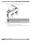
Chassis
Label Description
One Reader
10 Wire Connection
First Reader in a
5 Wire Connection
Second Reader in a
5 Wire Connection
NC
NO
1K,, 1%
1K,, 1%
1K,, 1%
1K,, 1%
187838