


2-12
Cisco Physical Access Gateway User Guide
OL-20932-02
Chapter 2 Installing and Configuring the Cisco Physical Access Gateway
Installing the Cisco Physical Access Gateway
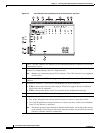
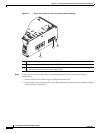
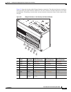
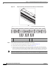
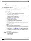
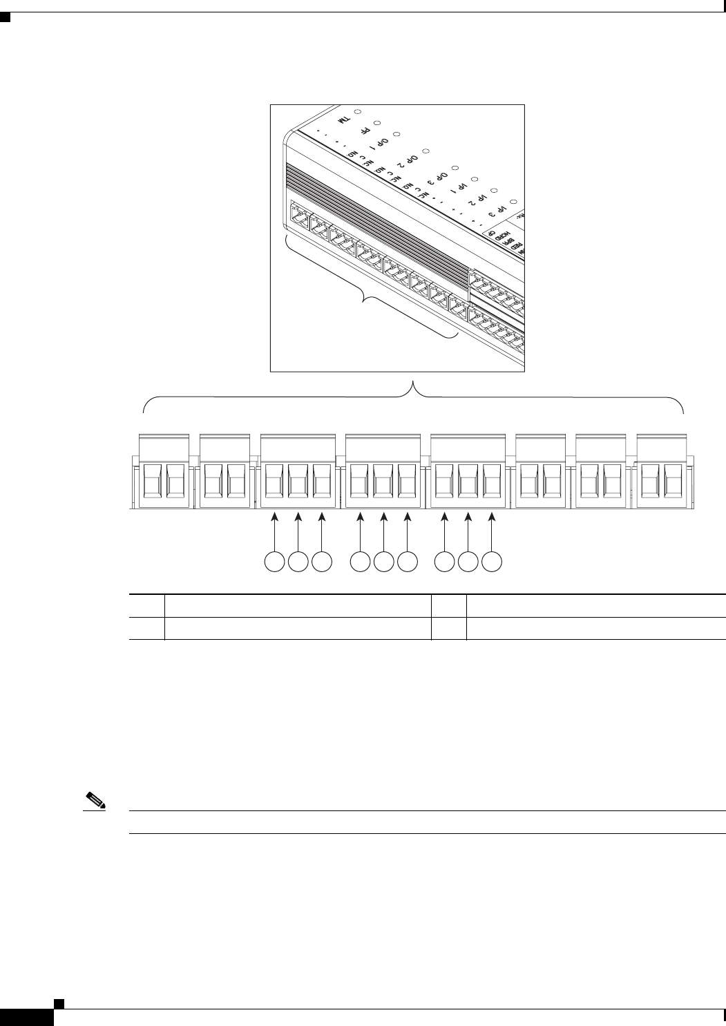
Figure 2-8 Output Connections: Cisco Physical Access Gateway and Reader Module
Step 6
Connect optional expansion modules to the Gateway, if necessary:
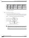
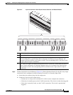
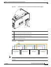
a. Insert a three-pin connector plug into the CAN1 port, as shown in Figure 2-9.
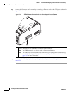
b. Connect the CAN wires to the CAN bus, as shown in Figure 2-10.
c. On the last device in the CAN bus, set the CAN terminator switch to ON. The CAN terminator
switch in included on the Reader, Input and Output modules only (the Gateway is always the first
device in the CAN bus). Set the terminator switch to OFF for all other modules in the CAN bus.
Note Modules are connected using the CAN1 interface. The CAN2 interface is not supported in this release.
1 Normally Open (N.O.) connection 3 Normally Closed (N.O.) connection
2 C
271593
31 2 31 2 31 2