


4-5
Cisco Physical Access Gateway User Guide
OL-20932-02
Chapter 4 Connecting a Cisco Input Module
Installing the Cisco Input Module
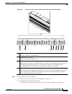
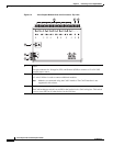
Status LEDs
Each input port includes a status LED that indicates the following information:
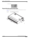
Installing the Cisco Input Module
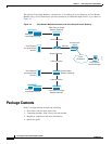
Install a Cisco Input Module is provide additional input connections for a Cisco Reader Module or
Gateway
Before You Begin
Verify the following:
• Verify that the module has access to a power source. See the “Power Options and Requirements”
section on page 1-12 for more information.
• Verify that you have the necessary mounting brackets or other hardware. See the “Mounting a
Gateway or Optional Module” section on page 1-14.
Procedure
To install the module, complete the following procedure:
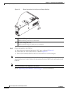
Step 1 Mount the module to a wall. See the “Mounting a Gateway or Optional Module” section on page 1-14
for more information.
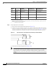
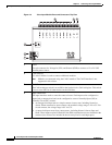
Step 2 Connect the module to the DC power source:
a. Insert a two-pin connector plug into the DC power port (Figure 4-5)
b. Connect the Voltage In (VIN) and ground (GND) wires.
See the “Power Options and Requirements” section on page 1-12 for more information.
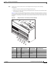
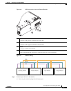
8 PF
Power fail input: an unsupervised input that raises a “power fail” alarm when the circuit is
open. Can be configured as an additional unsupervised port. The corresponding LED is red
when circuit is open (when no input is connected).
9 TM
Tamper input: an unsupervised input that raises a “tamper” alarm when the circuit is open.
Can be configured as an additional unsupervised port. The corresponding LED is red when
circuit is open (when no input is connected).
Table 4-1 Input Module LEDs
Status Description
OFF Input is not configured
GREEN Input is configured and in normal state
BLINKING GREEN Input is configured, and is receiving and alarm or other data.
BLINKING RED Input is configured, short
RED Input is configured, open