


2-13
Cisco Physical Access Gateway User Guide
OL-20932-02
Chapter 2 Installing and Configuring the Cisco Physical Access Gateway
Installing the Cisco Physical Access Gateway
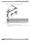
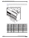
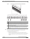
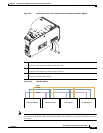
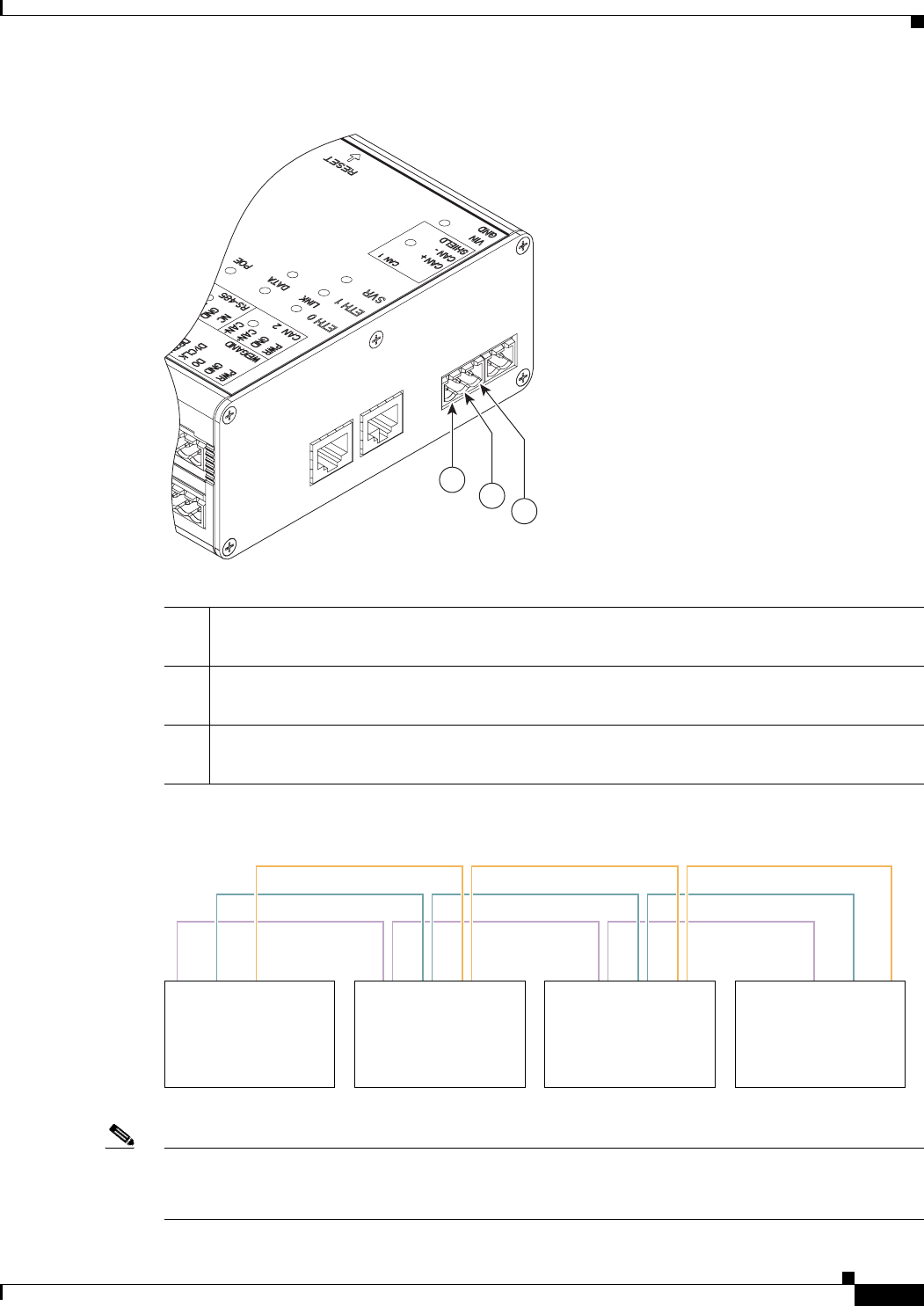
Figure 2-9 CAN1 Connections: Cisco Physical Access Gateway and Reader Module
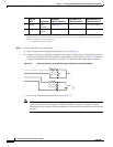
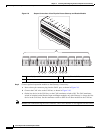
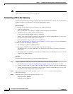
Figure 2-10 CAN Bus Wiring
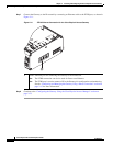
Note On the last device in the CAN bus, set the CAN terminator switch to ON. The CAN terminator switch
in included on the Reader, Input and Output modules only (the Gateway is always the first device in the
CAN bus).
1 CAN+
Connects to the positive terminal of the CAN bus.
2 CAN-
Connects to the negative terminal of the CAN bus.
3 Shield
Connects to GND and/or Shield.
271590
2
3
1
271589
Gateway Module Reader Module Input Module Output Module
CAN+
CAN-
Sheild