


4-4
Cisco Physical Access Gateway User Guide
OL-20932-02
Chapter 4 Connecting a Cisco Input Module
Physical Overview and Port Description
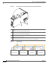
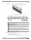
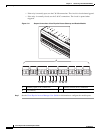
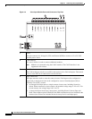
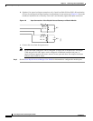
Figure 4-4 Cisco Input Module Ports and Connectors: Top View
1 Power
Two-pin connector for Voltage In (VIN) and Ground (GND) to connect a 12 to 24 VDC
external power source.
2 CAN interface
A 3-wire CAN bus is used to connect additional modules.
Note Modules are connected using the CAN1 interface. The CAN2 interface is not
supported in this release.
3 CAN Terminator
The CAN terminator switch is set to ON for the last device in a CAN wiring bus. This switch
is set to set to OFF for all other devices in the CAN bus.
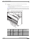
4 Input connections
Ten input interfaces used to sense the contact closure. Each input can be configured as
supervised or unsupervised and can be configured to sense a Normally Open (NO) or
Normally Closed (NC) contact.
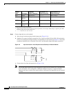
• An unsupervised input senses a simple contact closure state, including Normal or
Alarm. When connected to open contacts, the terminal voltage range is 4V to 5V. For
closed contacts, the voltage range is 0V to 0.7V.
• A supervised input senses four contact states, including Normal, Alarm, Open and
Short. These inputs require 1K End-Of-Line (EOL) termination resistors installed at the
contacts (two resistors are included in the accessory kits for each Input port).
4
5 6
1
2
3
187039