


2-4
Cisco Physical Access Gateway User Guide
OL-20932-02
Chapter 2 Installing and Configuring the Cisco Physical Access Gateway
Physical Overview and Port Description
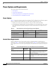
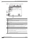
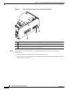
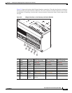
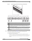
Figure 2-3 Cisco Physical Access Gateway Ports and Connectors: Top View
1 Power—Two-pin connector for Voltage In (VIN) and Ground (GND) to connect a 12 to 24 VDC
external power source.
2 CAN—A three-wire CAN bus is used to connect additional modules, including the Cisco Reader
Module, Cisco Input Module, and Cisco Output Module.
Note Modules are connected using the CAN1 interface. The CAN2 interface is not supported
in this release.
3 SVR (Server)—When the LED is steady green, the Gateway is connected to a Cisco PAM
appliance.
4 Fast Ethernet interfaces—There are two 10/100 BASE-TX RJ-45 connectors:
• ETH 0: connects the Gateway to the network. ETH 0 also supports Power over Ethernet
(PoE) for the device (optional).
• ETH 1: connects the device to a PC to access the device configuration web page.
5 Serial interface—The RS-485 interface is not supported in this release.
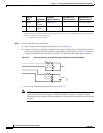
6 Wiegand interface—This interface can be configured as the following:
• One 10-pin Wiegand/clock and data reader interface to connect a single door reader.
• Two 5-pin Wiegand/clock and data interfaces to connect two door readers (for installations
where a 5-pin interface is sufficient).
Note Disconnect power from the Gateway or Reader module before connecting reader devices
to the modules. Connecting a reader device when the modules are powered can cause the
Gateway or Reader module to malfunction.
2 5 6 7 8 9 10
11
1
2
3
4
187039