


2-5
Cisco Physical Access Gateway User Guide
OL-20932-02
Chapter 2 Installing and Configuring the Cisco Physical Access Gateway
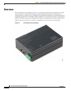
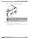
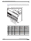
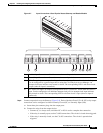
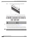
Physical Overview and Port Description
LED Status
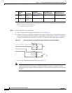
Table 2-1 describes the Gateway module status LEDs:
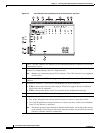
7 Input interfaces—Three input interfaces used to sense the contact closure. Each input can be
configured as supervised or unsupervised and can be configured to sense a Normally Open (NO)
or Normally Closed (NC) contact.
• An unsupervised input senses a simple contact closure state, including Normal or Alarm.
When connected to open contacts, the terminal voltage range is 4V to 5V. For closed
contacts, the voltage range is 0V to 0.7V.
• A supervised input senses four contact states, including Normal, Alarm, Open and Short.
These inputs require 1K End-Of-Line (EOL) termination resistors installed at the contacts
(two resistors are included in the accessory kits for each Input port).
8 Output interfaces—Three Form C (5A @ 30V) relay output interfaces. Each output connection
can be configured as either Normally Closed (NC) or Normally Open (NO).
• C & NO connection: The relay is normally open. The circuit is closed when triggered.
• C & NC connection: The relay is normally closed. The circuit is opened when triggered.
Notes:
• Install surge protection between the output device and the Cisco PAM module, as described
in the “Installing Surge Suppressors on Output Device Connections” section on page 1-13.
• Common (C) is always used, and either NC or NO is used to complete the connection.
• All Generic Output devices installed in Cisco PAM systems prior to release 1.1.0, were
connected to the Gateway, Reader, or Output modules with the wiring reversed. If upgrading
to Cisco PAM release 1.1.0 from an earlier release, disconnect all Generic Output devices
and do the following:
–
Connect Normally Open devices to the N.O. and C connectors on the Gateway, Reader,
or Output module.
–
Connect Normally Closed devices to the N.C. and C connectors on the Gateway, Reader,
or Output module.
9 PF—Power fail input: an unsupervised input that raises a “power fail” alarm when the circuit is
open. Can be configured as an additional unsupervised port. An unsupervised input indicates
only normal or alarm. The corresponding LED is red when circuit is open (when no input is
connected).
10 TM—Tamper input: an unsupervised input that raises a “tamper” alarm when the circuit is open.
Can be configured as an additional unsupervised port. An unsupervised input indicates only
normal or alarm. The corresponding LED is red when circuit is open (when no input is
connected).
11 Reset—Resets the device. See the “Resetting the Cisco Physical Access Gateway” section on
page 2-24 for more information.
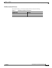
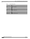
Table 2-1 Gateway LEDs
Status Description
SVR
Steady Green The Gateway is connected to a Cisco PAM appliance.