


5-4
Cisco Physical Access Gateway User Guide
OL-20932-02
Chapter 5 Connecting a Cisco Output Module
Physical Overview and Port Description
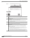
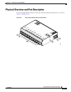
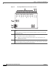
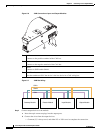
Figure 5-4 Cisco Output Module Ports and Connectors: Top View
1 Power
Two-pin connector for Voltage In (VIN) and Ground (GND) to connect a 12 to 24 VDC
external power source.
2 CAN interface
A 3-wire CAN bus is used to connect additional modules.
Note Modules are connected using the CAN1 interface. The CAN2 interface is not
supported in this release.
3 CAN terminator
The CAN terminator switch is set to ON for the last device in a CAN wiring bus. This switch
is set to set to OFF for all other devices in the CAN bus.
4
5 6
3
1
2
187045