


2-8
Cisco Physical Access Gateway User Guide
OL-20932-02
Chapter 2 Installing and Configuring the Cisco Physical Access Gateway
Installing the Cisco Physical Access Gateway
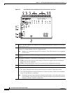
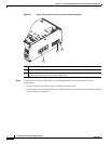
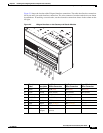
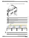
Figure 2-4 Power Connections for the Cisco Physical Access Gateway
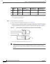
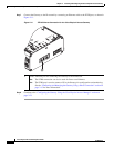
Step 3 Connect one or two door reader devices to the Wiegand interface using one of the following
configurations:
• Connect a single door reader using all 10 Wiegand interface pins.
• Connect one or two door readers using 5-pin Wiegand interface connections (for installations where
a 5-pin interface is sufficient).
1 DC power GND (ground)— Connects the DC ground wire to the Gateway.
2 DC power Voltage In (VIN)—Connects the DC Voltage In (VIN) wire to the Gateway.
3 ETH0 for PoE—Connects the Ethernet cable from the Access Layer switch to the Gateway. To
use this power option, the switch must support PoE.
271594
3
1
2