


2-9
Cisco Physical Access Gateway User Guide
OL-20932-02
Chapter 2 Installing and Configuring the Cisco Physical Access Gateway
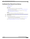
Installing the Cisco Physical Access Gateway
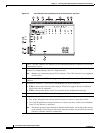
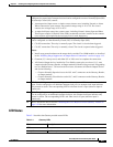
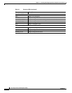
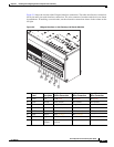
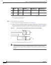
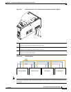
Figure 2-5 shows the location of the Wiegand interface connections. The table describes the connections
for 10-pin and 5-pin reader interface connections. The wire connectors from the reader device are shown
in parentheses. If attaching a second reader, use the alternative connections shown in the column on the
far right.
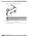
Figure 2-5 Wiegand Interface on the Gateway and Reader Modules
Chassis
Label Description
One Reader
10 Wire Connection
First Reader in a
5 Wire Connection
Second Reader in a
5 Wire Connection
1 PWR +12v PWR (red)
1
PWR (red) PWR (red)
2 GND Ground GND (black) GND (black) GND (black)
3 D0 Data 0 D0 (green) D0 (green) ----------
4 D1/CLCK Data 1 D1/CLCK (white) D1/CLCK (white) ----------
5 DRTN Shield DRTN (shield) DRTN (shield) DRTN (shield)
6 GRN Output
2
GRN (orange) GRN (orange) ----------
7 RED Output RED (brown) ----------
3
GRN (orange)
8 BPR Output
(Beeper)
BPR (yellow)
(yellow)
---------- ----------
271603
10
9
8
7
6
5
4
3
2
1