


5–24 Internal Processor Registers
21264/EV68A Hardware Reference Manual
Ibox IPRs
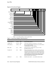
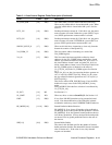
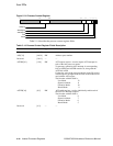
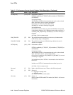
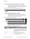
PCTR0[19:0] [47:28] RW Performance counter 0.
PCTR0 is enabled by I_CTL[PCT0_EN] and either I_CTL[SPCE] or
PCTX[PPCE].
In Aggregate mode:
When enabled, PCTR0 is incremented at each cycle by the selected
input. (See Section 6.10.2 for more information.)
On overflow, if enabled by IER_CM[PCEN0],
ISUM[PC0] is set and an interrupt is triggered.
In ProfileMe mode:
On overflow, a count window is opened and PCTR0 is incremented
as described in Section 6.10.3. When the count window overflows, if
enabled by IER_CM[PCEN0], ISUM[PC0] is set and an interrupt is
triggered.
See Table 5–16 for counter modes.
PM_STALLED [27] RO The profiled instruction stalled for at least one cycle between the
fetch and map stages of the pipeline.
PM_KILLED_BM [26] RO The profiled instruction was killed during or before the cycle in
which it was mapped.
PCTR1[19:0] [25:6] RW Performance counter 1.
PCTR1 is enabled by I_CTL[PCT1_EN] and either I_CTL[SPCE] or
PCTX[PPCE].
In Aggregate mode:
When enabled, PCTR1 is incremented at each cycle by the selected
input. (See Section 6.10.2 for more information.)
On overflow, if enabled by IER_CM[PCEN1], ISUM[PC1] is set and
an interrupt is triggered.
In ProfileMe mode, how PCTR1 is incremented is described in Sec-
tion 6.10.3.
In either case, PCTR1 is incremented no more than 1 per cycle.
See Table 5–16 for counter modes.
Reserved [5] RO Reads to this field return zero. Writes to this field are ignored.
SL0 [4] RW Selector 0.
0 = Aggregate counting mode
1=ProfileMemode
See Table 5–16 for more information.
SL1[1:0] [3:2] RW Selector 1.
Selects counter PCTR0 and PCTR1 modes. See Table 5–16 for more
information.
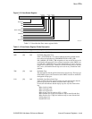
Table 5–15 Performance Counter Control Register Fields Description (Continued)
Name Extent Type Description