


7–2 Initialization and Configuration
21264/EV68A Hardware Reference Manual
Power-Up Reset Flow and the Reset_L and DCOK_H Pins
1. The clock forwarding and system clock ratio configuration information is loaded
onto the 21264/EV68A. See Section 7.1.2.
2. The internal PLL is ramped up to operating frequency.
3. The internal arrays built-in self-test (BiST) is run, followed by Icache initialization
using an external serial ROM (SROM) interface.
The 21264/EV68A systems, unlike the Alpha 21064 and 21164 microprocessor
systems, are required to have an SROM. The SROM provides the only means to
configure the system port, and the SROM pins can be used as a software-controlled
UART.
The Icache must contain PALcode that starts at location 0x780. This code is used to
configure the 21264/EV68A IPRs as necessary before causing any offchip read or
write commands. This allows the 21264/EV68A to be configured to match the
external system implementation.
4. After configuring the 21264/EV68A, control can be transferred to code anywhere
in memory, including the noncacheable regions. The Icache can be flushed by a
write operation to the ITB invalidate-all register after control is transferred. This
transfer of control should be to addresses not loaded in the Icache by the SROM
interface or the Icache may provide unexpected instructions.
5. Typically, any state required by the PALcode is initialized and then the console is
started (switching out of PALmode and into native mode). The console code initial-
izes and configures the system and boots an operating system from an I/O device
such as a disk or the network.
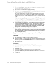
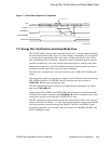
Figure 7–1 shows the sequence of events at power-up, or cold reset. In Figure 7–1, note
the following symbols for constraints and information:
Constraints:
Information:
A Setup (A0) and hold (A1) for IRQ’s to be latched by DCOK (2 ns for each).
B Enough time for Reset_L to propagate through 5 stages of RESET synchronizer (clocked by the inter-
nal framing clock, which is driven by EV6Clk_x). Worst case for the 21264/EV68A would be 5x8x15
= 600 GCLK cycles.
C Min = 1 FrameClk cycle.
a 8 GCLK cycles from DCOK assertion to first “real” EV6Clk_x cycle.
b Approximately 525 GCLK cycles for external framing clock to be sampled and captured.
c1FrameClk_x cycle.
d3FrameClk_x cycles.
e Approximately 264 GCLK cycles to prevent first command from appearing too early.
f Approximately 700,000 GCLK cycles for BiST + approximately 100,000 GCLK cycles fixed time +
approximately 50,000 GCLK cycles per line of Icache for SROM load.
g16GCLKcycles.