


7–6 Initialization and Configuration
21264/EV68A Hardware Reference Manual
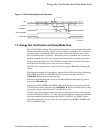
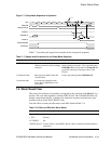
Power-Up Reset Flow and the Reset_L and DCOK_H Pins
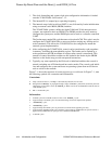
7.1.3 PLL Ramp Up
After the configuration is loaded through the IRQ_H pins, the next phase in the power
up flow is the internal PLL ramp up sequence. Ramping up of the PLL is required to
guarantee that the dynamic change in frequency will not cause the supply on the 21264/
EV68A to fall due to the supply loop inductance. Clock control circuitry steps GCLK
from power-up/reset clocking to 1/16
th
operating frequency, to ½ operating frequency,
and finally normal operating frequency.
After the assertion of DCOK_H, the 21264/EV68A waits for the deassertion of
Reset_L from the system while the PLL attempts to achieve a lock. The PLL internal
ramp dividers are set to divide down the input clock by 16 and the PLL attempts to
achieve lock against an effective input frequency of ClkIn_x/16. Once lock is
achieved, the actual internal frequency (GCLK) is ClkIn_x*(Y
div
divisor value)/16.
There should be a minimum delay of 100 ms between the assertion of DCOK_H and
the deassertion of Reset_L to allow for this locking The reset state machine is in the
WAIT_NOMINAL state.
After the deassertion of Reset_L, the reset state machine goes into the RAMP1 state.
The 21264/EV68A ramps the internal frequency, by changing the effective input fre-
quency of the PLL to ClkIn_x/2 for a sufficient lock interval (at most, 20 µsat400
MHz). The state machine then goes into the RAMP2 state, changing the effective input
frequency to ClkIn/1 for an additional lock interval (about 20 µs). The lock periods are
generated by the internal duration counter, which is driven by GCLK. The counter
counts 4108 GCLK cycles during the ClkIn_x/2 lock interval. Note that GCLK is pro-
duced by the output of the PLL, which is locking to an input clock which is 1/2 of the
operating frequency — therefore, the 4108 cycle interval constitutes a 6-20 µs interval
when the operating frequency is 400–1250 MHz. Then, the counter counts 8205 GCLK
cycles during the ClkIn_x/1 lock interval.
7.1.4 BiST and SROM Load and the TestStat_H Pin
The 21264/EV68A uses the deassertion of ClkFwdRst_H (which must be deasserted
for a minimum of one FrameClk_H cycle and then reasserted) to begin built-in self-
test (BiST). The reset state machine goes into the WAIT_BiST state. Details on BiST
are given in Chapter 11. The power-up BiST lasts approximately 700,000 cycles. The
result of the self-test is made available on the TestStat_H pin. The pin is forced low by
the system reset. It is then forced high during BiST.
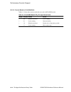
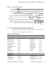
DCOK_H Continuous input When deasserted, initializes the internal 21264/
EV68A reset state machine and keeps the PLL
internal oscillator running at a nominal speed.
Assertion, which implies power to the 21264/
EV68A is good, causes configuration informa-
tion to be sampled.
—
1
The maximum permissible instantaneous change in ClkIn_x frequency is 333 MHz (to prevent cur-
rent spikes).
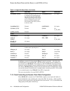
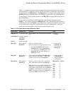
Table 7–3 Pin Signal Names and Initialization State (Continued)
Signal Name Sample Time Function Value