


10–2 Thermal Management
21264/EV68A Hardware Reference Manual
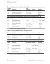
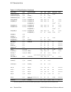
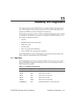
Operating Temperature
Table 10–2 lists the values for the center of heat-sink-to-ambient (θ
c
a) for the 21264/
EV68A 587-pin PGA. Tables 10–3 through 10–6 show the allowable T
a
(without
exceeding T
c
) at various airflows.
Table 10–2 θ
ca
at Various Airflows for 21264/EV68A
Airflow (linear ft/min) 200 400 600 800
θ
c
a with heat sink type 1 (°C/W) 0.68 0.42 0.36 0.33
θ
c
a with heat sink type 2 (°C/W) 0.62 0.35 0.28 0.25
θ
c
a with heat sink type 3
1
(°C/W)
1
Heatsinktype3hasa80mm× 80 mm × 15 mm fan attached.
—0.32—
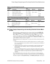
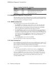
Table 10–3 Maximum T
a
for 21264/EV68A @ 750 MHz and @ 1.7 V with Various Airflows
Airflow (linear ft/min) 200 400 600 800
Maximum T
a
with heat sink type 1 (°C) 40.0 55.6 59.2 61.0
Maximum T
a
with heat sink type 2 (°C) 43.6 59.8 64.0 65.8
Maximum T
a
with heat sink type 3
1
(°C)
1
Heatsinktype3hasa80mm× 80 mm × 15 mm fan attached.
— 61.6 —
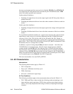
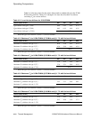
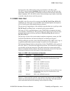
Table 10–4 Maximum T
a
for 21264/EV68A @ 833 MHz and @ 1.7 V with Various Airflows
Airflow (linear ft/min) 200 400 600 800
Maximum T
a
with heat sink type 1 (°C) 33.0 50.4 54.4 56.5
Maximum T
a
with heat sink type 2 (°C) 37.0 55.1 59.8 61.8
Maximum T
a
with heat sink type 3
1
(°C)
1
Heatsinktype3hasa80mm× 80 mm × 15 mm fan attached.
— 57.1 —
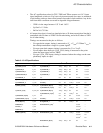
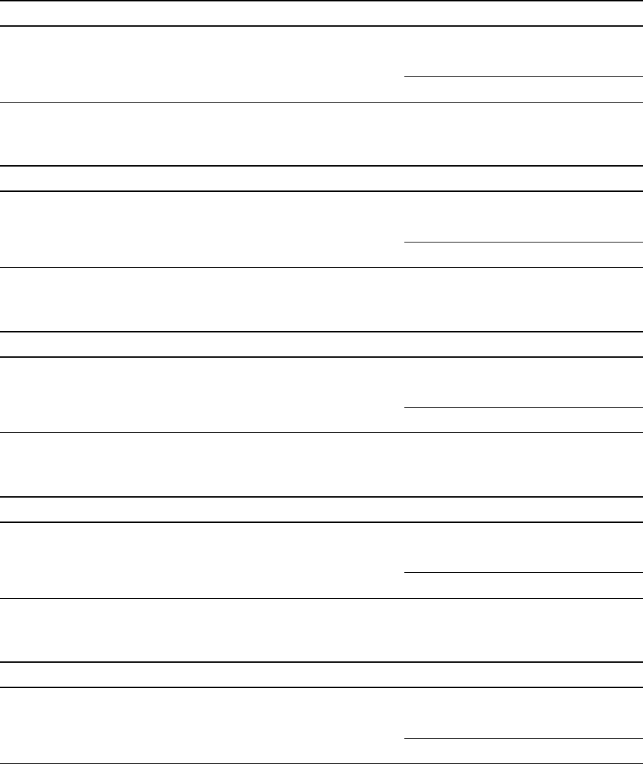
Table 10–5 Maximum T
a
for 21264/EV68A @ 875 MHz and @ 1.7 V with Various Airflows
Airflow (linear ft/min) 200 400 600 800
Maximum T
a
with heat sink type 1 (°C) 30.0 48.2 52.4 54.5
Maximum T
a
with heat sink type 2 (°C) 34.2 53.1 58.0 60.1
Maximum T
a
with heat sink type 3
1
(°C)
1
Heatsinktype3hasa80mm× 80 mm × 15 mm fan attached.
— 55.2 —
Table 10–6 Maximum T
a
for 21264/EV68A @ 940 MHz and @ 1.7 V with Various Airflows
Airflow (linear ft/min) 200 400 600 800
Maximum T
a
with heat sink type 1 (°C) 25.0 44.5 49.0 51.3
Maximum T
a
with heat sink type 2 (°C) 29.5 49.8 55.0 57.3
Maximum T
a
with heat sink type 3
1
(°C)
1
Heatsinktype3hasa80mm× 80 mm × 15 mm fan attached.
— 52.0 —