6-6 Installation and Troubleshooting Guide
-!, !#'
)8
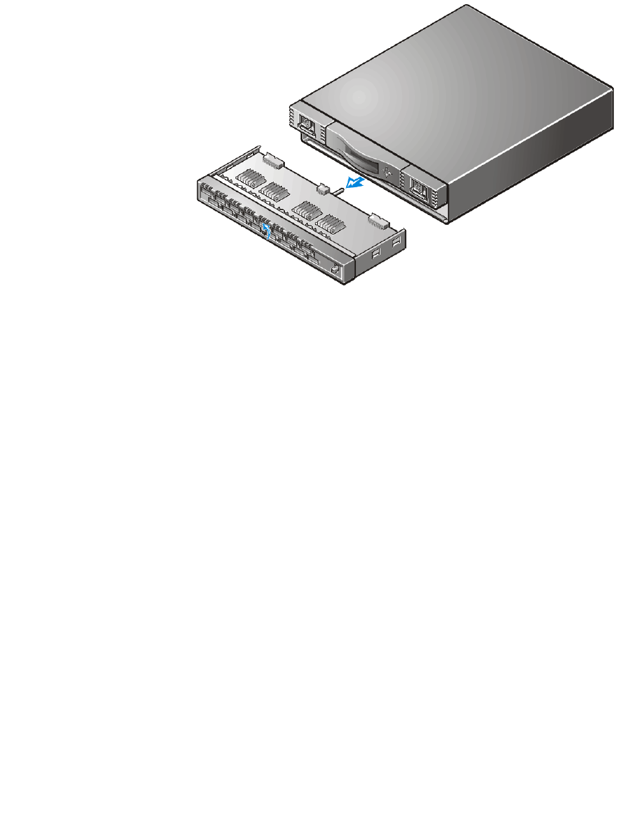
1. Insert the system board module into the switch’s cavity and tighten the captured
screw until the module is fully inserted.
2. Reconnect the power supply connector(s).
3. Reinstall the GBICs.
See “Installing a GBIC Module” found earlier in this chapter for instructions.
4. Reconnect all external cabling.
5. Turn on the switch’s power.
The switch automatically runs POST.
6. Check for error messages by issuing the Te l n e t command.
$
Replacing the chassis involves removing the switch’s GBICs, system board, power
supply(s), fan assembly, and then reinstalling them into the new chassis assembly.
9
#1 Phillips-head screwdriver
#6 flat-head screwdriver


