


2-4 Installation and Troubleshooting Guide
Each connection is full duplex with transmissions up to 1 Gbps simultaneously, in
both directions, between the fabric and fabric-connected devices.
##%%
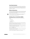
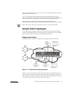
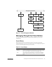
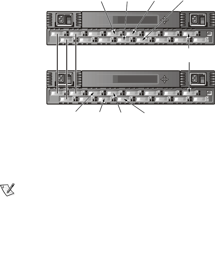
The two-switch topology increases the number of connections and aggregate fabric
bandwidth, as shown schematically in Figure 2-2. The switches are shown physically
connected although the connections are transparent in the fabric. Functionally, the
devices appear to be connected together directly.
!"
#
When a fabric is initiated, or when a new switch is added to the fabric, the switches
determine a least-cost path for each destination switch. This is done dynamically each
time the fabric configuration changes and the results are stored in the switch’s inter-
nal routing tables.
NOTE: After a path has been determined, it is not rerouted, even though traffic vol-
ume may change over time, for each path to maintain in-order delivery. If the link fails,
the path is rerouted.
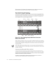
In Figure 2-2, three connections are shown between Switch A and Switch B. This
connection gives an aggregate bandwidth of six Gbps—in other words, three 1-Gbps,
full-duplex connections. Increasing bandwidth between switches is done by adding
additional connections between the switches.
In addition to the bandwidth, redundant connections between the switches in
Figure 2-2 provide a high-bandwidth, fault-tolerant fabric.
Switch A
Switch B
E_Port
E_Port
RAID A
RAID B HOST3 HOST4
HOST1
HOST2 RAID A
RAID B
JBOD A
HOST5