


Installing System Components 95
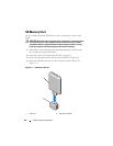
Installing Memory Modules
CAUTION: Only trained service technicians are authorized to remove the system
cover and access any of the components inside the system. See your Product
Information Guide for complete information about safety precautions, working
inside the computer, and protecting against electrostatic discharge.
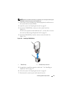
CAUTION: The memory modules are hot to the touch for some time after the
system has been powered down. Allow time for the memory modules to cool
before handling them. Handle the memory modules by the card edges and avoid
touching the components on the memory module.
1
Turn off the system, including any attached peripherals, and disconnect
the system from the electrical outlet.
2
Open the system. See "Opening the System" on page 65.
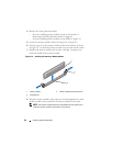
3
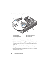
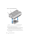
Remove the PEM (four-processor configurations) or PEM shell (two-
processor configurations). See "Removing the PEM or PEM Shell" on
page 73.
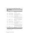
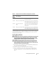
128 GB Sixteen 8 GB, 667 MHz A1, A2, A3, A4, B1, B2, B3, B4, C1, C2, C3,
C4, D1, D2, D3, D4
128 GB Thirty-two 4 GB, 667 MHz A1, A2, A3, A4, A5, A6, A7, A8, B1, B2, B3,
B4, B5, B6, B7, B8, C1, C2, C3, C4, C5, C6,
C7, C8, D1, D2, D3, D4, D5, D6, D7, D8
192 GB Twenty-four 8 GB, 667
MHz
A1, A2, A3, A4, A5, A6, B1, B2, B3, B4, B5,
B6, C1, C2, C3, C4, C5, C6, D1, D2, D3,
D4, D5, D6
256 GB Thirty-two 8 GB, 667 MHz A1, A2, A3, A4, A5, A6, A7, A8, B1, B2, B3,
B4, B5, B6, B7, B8, C1, C2, C3, C4, C5, C6,
C7, C8, D1, D2, D3, D4, D5, D6, D7, D8
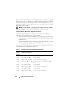
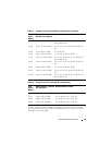
Table 3-2. Examples of Four-Processor Memory Configurations (continued)
Total
System
Memory
Memory Modules – Number,
Size and Speed
Memory Module Locations
* 2-GB 800 MHz and 4-GB 800 MHz memory modules will be supported when
available 800-MHz memory modules are limited to a maximum of four modules per
processor. If more than four modules are installed per processor, the system will
downclock them to 667 MHz.