


System Overview 1-11
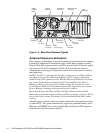
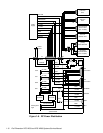
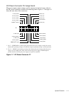
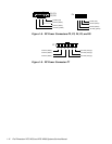
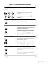
DC Power Connector Pin Assignments
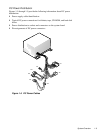
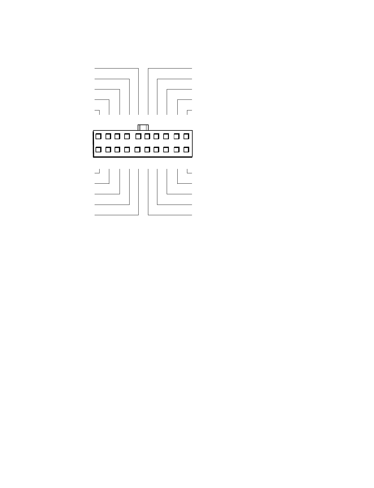
The power-supply output voltages can be measured at the back (wire side) of
the DC power connectors without disconnecting them. Figures 1-7 through 1-9
show the wire side of the connectors.
1 Pin 5 — PWRGOOD is a status signal generated by the power supply to notify the system
that the DC operating voltages are within the ranges required for proper system operation.
2 Pin 11 — PSON# is activated by pressing and releasing the power button while the power
supply is in its standby state. This action connects the power supply’s PSON# input to
ground, thereby switching the power supply to its full-on condition.
Figure 1-7. DC Power Connector P1
11
1
PWRGOOD
1
(gray)
–12 VDC (blue)
+12 VDC (yellow)
+5 VFP (purple)
common (black)
2 345678910
12 13 14 15 16 17 18 19 20
P1
+5 VDC (red)
+5 VDC (red)
+5 VDC (red)
+5 VDC (red)
+5 VDC (red)
+5 VDC (red)
common (black)
common (black)
common (black)
PSON#
2
(brown)
common (black)
common (black)
common (black)
–5 VDC (white)
not connected