


Removing and Replacing Parts 4-17
S
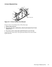
ystem Board Components
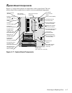
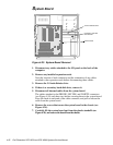
Figure 4-17 shows the locations of components on the system board. The sub-
sections that follow explain how to remove various system board components.
Figure 4-17. System Board Components
parallel port
connector (PARALLEL)
mouse connector
(MOUSE)
diskette-drive interface
connector (FLOPPY)
power input connector
(POWER)
secondary EIDE channel
connector (SEC IDE)
ISA expansion-card
connectors (ISA1,
ISA2, and ISA3)
keyboard connector
(KEYBRD)
SEC cartridge
connector (SLOT 1)
system board
jumpers
primary EIDE channel
connector (PRI IDE)
PCI expansion-card
connectors (PCI1,
PCI2, PCI3, and PCI4)
control panel
connector (J9D1)
battery socket (BT9M1)
serial port
connector (SER1)
SIMM sockets
(J6J1, J6J2, J7J1, and J7J2)
microprocessor fan
connector (J8L1)
wave-table upgrade
connectors (J7C1
and J7D1)
SCSI hard-disk drive
access indicator cable
connector (J8D1)
3.3-V power
input connector
(J7M1)
USB connectors
(USB)
integrated audio
controller jacks
(LINE OUT, LINE
IN, and MIC IN)
MIDI/game port
(GAME/AUDIO)
CD-ROM drive
audio cable
connector (CDROM)