


DES-3326 Layer 3 Fast Ethernet Switch User’s Guide
3
IDENTIFYING EXTERNAL COMPONENTS
This chapter describes the front panel, rear panel, optional plug-in modules, and LED indicators of the
DES-3326.
Front Panel
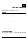
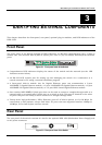
The front panel of the Switch consists of LED indicators, an RS-232 communication port, a slide-in
module slot, one switched MDI-X/MDI-II uplink port, and 23 (10/100 Mbps) Ethernet/Fast Ethernet
ports.
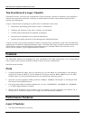
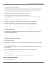
Figure 3-1. Front panel view of the Switch
♦ Comprehensive LED indicators display the status of the switch and the network (see the LED
Indicators section below).
♦ An RS-232 DCE console port for setting up and managing the switch via a connection to a
console terminal or PC using a terminal emulation program.
♦ A front-panel slide-in module slot for Gigabit Ethernet ports can accommodate a 2-port
1000BASE-T Gigabit Ethernet module, a 2-port 1000BASE-SX Gigabit Ethernet module, a 2-port
1000BASE-LX Gigabit Ethernet module, or a 2-port GBIC-based Gigabit Ethernet module.
♦ One switched MDI-X/MDI-II Uplink port that can be used to connect a straight-through cable or a
crossed cable to a normal (non-Uplink) port on a switch or hub. This port is identical to the other
23 ports except for the ability to use a crossed or a straight-through cable.
♦ Twenty-three high-performance, NWay Ethernet ports all of which operate at 10/100 Mbps for
connections to end stations, servers and hubs. All ports can auto-negotiate between 10Mbps or
100Mbps, full or half duplex, and flow control.
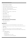
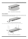
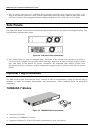
Rear Panel
The rear panel of the switch consists of a slot for the optional DPS-1000 (Redundant Power Supply) and
an AC power connector.
Figure 3-2. Rear panel view of the Switch
18