


DES-3326 Layer 3 Fast Ethernet Switch User’s Guide
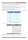
An example is presented below:
VLAN Name VID Switch Ports
System (default) 1 5, 6, 7, 8, 21, 22, 23, 24
Engineer 2 9, 10, 11, 12
Marketing 3 13, 14, 15, 16
Finance 4 17, 18, 19, 20
Sales 5 1, 2, 3, 4
Backbone 6 25, 26
Table 6-3. VLAN Example – Assigned Ports
In this case, 6 IP interfaces are required, so a CIDR notation of 10.32.0.0/11 (or a 11-bit) addressing
scheme will work. This addressing scheme will give a subnet mask of
11111111.11100000.00000000.00000000 (binary) or 255.224.0.0 (decimal).
Using a 10.xxx.xxx.xxx IP address notation, the above example would give 6 network addresses and 6
interfaces.
Any IP address from the allowed range of IP addresses for each interface can be chosen as an IP
address for an IP interface on the switch.
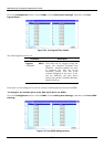
For this example, we have chosen the next IP address above the network address for the IP interface’s
IP Address:
VLAN Name VID Network Number IP Address
System (default) 1 10.32.0.0 10.32.0.1
Engineer 2 10.64.0.0 10.64.0.1
Marketing 3 10.96.0.0 10.96.0.1
Finance 4 10.128.0.0 10.128.0.1
Sales 5 10.160.0.0 10.160.0.1
Backbone 6 10.192.0.0 10.192.0.1
Table 6-4. VLAN Example – Assigned IP Interfaces
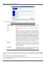
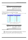
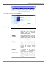
The 6 IP interfaces, each with an IP address (listed in the table above), and a subnet mask of
255.224.0.0 can be entered into the Setup IP Interface window.
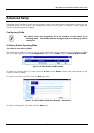
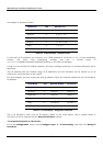
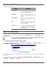
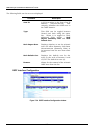
To setup IP Interfaces on the switch:
Go to the Configuration menu, select Configure Layer 3 – IP Networking, and then click Setup IP
Interfaces:
213