


DES-3326 Layer 3 Fast Ethernet Switch User’s Guide
Although the STP can elect a root bridge, a well-designed network will have an identifiable root for each
VLAN. Careful setup of the STP parameters will lead to the selection of this best switch as the root for
each VLAN. Redundant links can then be built into the network. STP is well suited to maintaining
connectivity in the event of a device failure or removal, but is poorly suited to designing networks.
Know which links are redundant.
Organize the redundant links and tune the port cost parameter of STP to force those ports to be in the
blocking state.
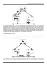
For each VLAN, know which ports should be blocking in a stable network. A network diagram that
shows each physical loop in the network and which ports break which loops is extremely helpful.
Minimize the number of ports in the blocking state.
A single blocking port transitioning to the forwarding state at an inappropriate time can cause a large
part of a network to fail. Limiting the number of blocked ports help to limit the risk of an inappropriate
transition.
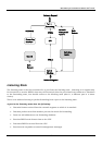
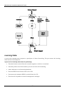
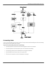
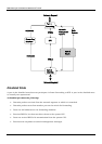
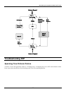
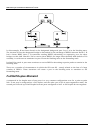
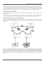
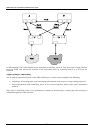
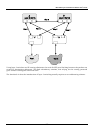
This is a common network design. The switches C and D have redundant links to the backbone
switches A and B using trunks. Trunks, by default, carry all the VLAN traffic from VLAN 1 and VLAN 2.
So switch C is not only receiving traffic for VLAN 1, but it is also receiving unnecessary broadcast and
multicast traffic for VLAN 2. It is also blocking one port for VLAN 2. Thus, there are three redundant
paths between switches A and B and two blocked ports per VLAN. This increases the chance of a data
loop.
276