


DES-3326 Layer 3 Fast Ethernet Switch User’s Guide
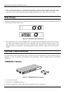
♦ The AC power connector is a standard three-pronged connector that supports the power cord.
Plug-in the female connector of the provided power cord into this socket, and the male side of the
cord into a power outlet. Supported input voltages range from 100 ~ 240 VAC at 50 ~ 60 Hz.
Side Panels
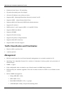
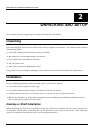
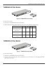
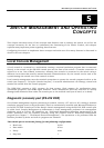
The right side panel of the Switch contains two system fans (see the top part of the diagram below). The
left side panel contains heat vents.
Figure 3-4. Side panel views of the Switch
♦ The system fans are used to dissipate heat. The sides of the system also provide heat vents to
serve the same purpose. Do not block these openings, and leave at least 6 inches of space at the
rear and sides of the switch for proper ventilation. Be reminded that without proper heat
dissipation and air circulation, system components might overheat, which could lead to system
failure.
Optional Plug-in Modules
The DES 3326 24-port Fast Ethernet Layer 3 Switch is able to accommodate a range of optional plug-in
modules in order to increase functionality and performance. These modules must be purchased
separately.
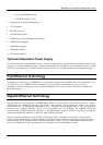
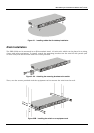
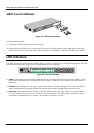
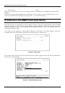
1000BASE-T Module
Figure 3-5. 1000BASE-TX two-port module
♦ Front-panel module.
♦ Connects to 1000BASE-T devices.
♦ Supports Category 5e UTP or STP cable connections of up to 100 meters.
19