


DES-3326 Layer 3 Fast Ethernet Switch User’s Guide
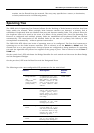
User-Changeable STA Parameters
The factory default setting should cover the majority of installations. However, it is advisable to keep
the default settings as set at the factory; unless, it is absolutely necessary. The user changeable
parameters in the Switch are as follows:
• Priority A Priority for the switch can be set from 0 to 65535. 0 is equal to the highest
Priority.
• Hello Time The Hello Time can be from 1 to 10 seconds. This is the interval between two
transmissions of BPDU packets sent by the Root Bridge to tell all other Switches that it is
indeed the Root Bridge. If you set a Hello Time for your Switch, and it is not the Root Bridge,
the set Hello Time will be used if and when your Switch becomes the Root Bridge.
Note: The Hello Time cannot be longer than the Max. Age. Otherwise, a configuration error will occur.
• Max. Age The Max. Age can be from 6 to 40 seconds. At the end of the Max. Age, if a BPDU
has still not been received from the Root Bridge, your Switch will start sending its own BPDU
to all other Switches for permission to become the Root Bridge. If it turns out that your
Switch has the lowest Bridge Identifier, it will become the Root Bridge.
• Forward Delay Timer The Forward Delay can be from 4 to 30 seconds. This is the time any
port on the Switch spends in the listening state while moving from the blocking state to the
forwarding state.
Note: Observe the following formulas when setting the above parameters:
Max. Age ≤ 2 x (Forward Delay - 1 second)
Max. Age ≥ 2 x (Hello Time + 1 second)
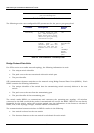
• Port Priority A Port Priority can be from 0 to 255. The lower the number, the greater the
probability the port will be chosen as the Root Port.
• Port Cost A Port Cost can be set from 1 to 65535. The lower the number, the greater the
probability the port will be chosen to forward packets.
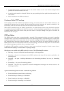
Illustration of STP
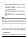
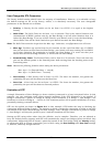
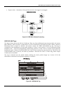
A simple illustration of three Bridges (or three switches) connected in a loop is depicted below. In this
example, you can anticipate some major network problems if the STP assistance is not applied. If
Bridge A broadcasts a packet to Bridge B, Bridge B will broadcast it to Bridge C, and Bridge C will
broadcast it to back to Bridge A ... and so on. The broadcast packet will be passed indefinitely in a loop,
potentially causing a network failure.
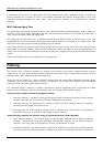
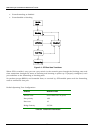
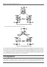
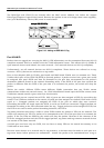
STP can be applied as shown in Figure 2-4. In this example, STP breaks the loop by blocking the
connection between Bridge B and C. The decision to block a particular connection is based on the STP
calculation of the most current Bridge and Port settings. Now, if Bridge A broadcasts a packet to Bridge
C, then Bridge C will drop the packet at port 2 and the broadcast will end there.
Setting-up STP using values other than the defaults, can be complex. Therefore, you are advised to
keep the default factory settings and STP will automatically assign root bridges/ports and block loop
connections. Influencing STP to choose a particular switch as the root bridge using the Priority setting,
or influencing STP to choose a particular port to block using the Port Priority and Port Cost settings
is, however, relatively straight forward.
34