


User Instructions UM1M820BNA
Spec No. 1M820BNA (Model M820B) Issue AH, March 4, 2013
Spec No. 1M820DNA (Model M820D)
Chapter 1. Introduction 5
This document is property of Emerson Network Power, Energy Systems, North America, Inc. and contains confidential and proprietary information owned by Emerson Network Power, Energy
Systems, North America, Inc. Any copying, use, or disclosure of it without the written permission of Emerson Network Power, Energy Systems, North America, Inc. is strictly prohibited.
Battery Charge Temperature Compensation
The ACU+ Controller can be programmed to automatically increase or decrease system output voltage to
maintain battery float current as battery temperature decreases or increases, respectively. Battery life can
be extended when an optimum charge voltage to the battery with respect to temperature is maintained.
Temperature is monitored by a sensor mounted on the battery. See your power system documentation for
temperature sensor information. You can also set High2, High1, and Low compensation temperature
alarms.
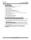
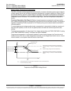
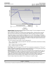
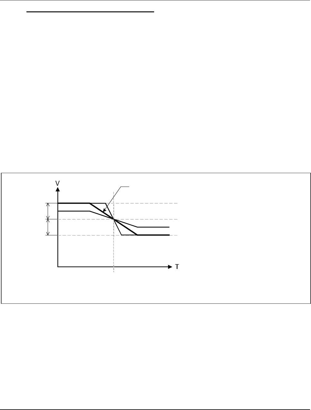
Functional Description (See Figure 2): Battery charge temperature compensation adds a correction
term, related to the temperature of the batteries, to the nominal value of the system voltage. The degree of
regulation (TempComp Coeff), expressed in mV/°C/battery string, can be set per battery manufacturer
recommendations.
To protect batteries and voltage-sensitive loads, compensation is automatically limited to a maximum of
two volts (48V systems) or one volt (24 volt systems) above or below the nominal output level (float
setting).
Temperature compensation will also clamp if the voltage reaches either the TEMP COMP MAX V setting
or the TEMP COMP MIN V setting. This feature can also be disabled.
Temperature compensation is automatically disabled if communication between the Controller and all
rectifiers is lost, a DC over or under voltage alarm activates, a low voltage disconnection occurs, manual
mode is entered, or the system enters the boost or test modes.
Figure 2
Temperature Compensated Voltage Control
TempComp Coeff
setting (mV/°C).
nom
T
nom
T
V
nom
V
high
V
low
Upper voltage level where temperature compensation
clamps the voltage. Limited to the TEMP COMP MAX V
setting.
Nominal voltage (voltage at nominal temperature).
Lower voltage level where temperature compensation
clamps the voltage. Limited to the TEMP COMP MIN V
setting.
Nominal temperature (no temperature compensation is done at this temperature).
This is the Temp Comp setting.
1V Max (24V System)
2V Max (48V System)
1V Max (24V System)
2V Max (48V System)