User Instructions UM1M820BNA
Spec No. 1M820BNA (Model M820B) Issue AH, March 4, 2013
Spec No. 1M820DNA (Model M820D)
Chapter 1. Introduction 1
This document is property of Emerson Network Power, Energy Systems, North America, Inc. and contains confidential and proprietary information owned by Emerson Network Power, Energy
Systems, North America, Inc. Any copying, use, or disclosure of it without the written permission of Emerson Network Power, Energy Systems, North America, Inc. is strictly prohibited.
CHAPTER 1. INTRODUCTION
1.1 Preface
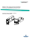
These instructions describe the complete functionality of the ACU+ Controller. Some functionality is
dependent on hardware connected to the ACU+ Controller. Your system may not utilize all the
functionality described.
Refer also to the ACU+ Configuration Drawing (C-drawing) furnished with your system for a list of factory
default settings.
1.2 Overview
The ACU+ Controller performs the following functions.
Rectifier Control, including an Energy Optimization Mode
Converter Control
System Components Monitoring and System Alarms Generation
(including recording alarms in logs)
Operating Data Acquisition and Data Logs
Battery Management
Intelligent Power Matching (Energy Optimization Mode)
Power Split Feature
Diesel Management Feature
PLC (Programmable Logic Controller) Function
Supervisory Module (SM Modules) Monitoring
Hybrid Control Function
Maximum Current Limit Function
The ACU+ controls the system automatically via configured parameters.
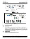
A User interfaces with the ACU+ Controller locally using the local keypad and LCD display or
locally/remotely using the WEB Interface.
The ACU+ Controller can also be accessed via SNMP (v1 and v2).


