User Instructions UM1M820BNA
Spec No. 1M820BNA (Model M820B) Issue AH, March 4, 2013
Spec No. 1M820DNA (Model M820D)
Chapter 3. Local Display Menus 85
This document is property of Emerson Network Power, Energy Systems, North America, Inc. and contains confidential and proprietary information owned by Emerson Network Power, Energy
Systems, North America, Inc. Any copying, use, or disclosure of it without the written permission of Emerson Network Power, Energy Systems, North America, Inc. is strictly prohibited.
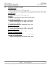
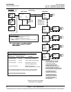
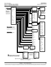
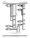
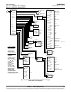
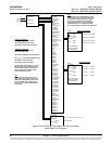
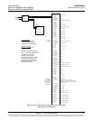
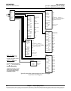
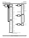
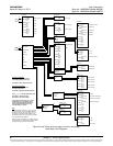
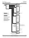
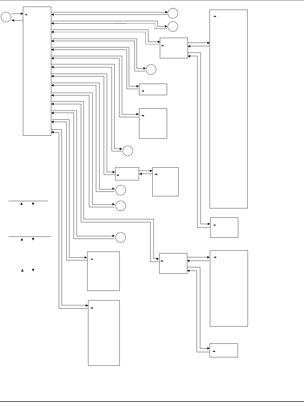
Figure 8 (cont’d from previous page, cont’d on next page)
Local Menu Flow Diagrams
Settings
Alarm Setting
Power System
Rectifier
Battery
BattFuseUnit
DC
LVD
AC
EIB
SMDU
Converter
SMTemp
Communication
Controller
ESC
B1
B
B3
B2
ENT
ENT
ENT
ENT
ENT
ENT
ESC
ESC
ESC
B5
B4
ESC
ESC
ESC
ESC
ESC
ESC
ESC
ENT
ENT
ENT
ENT
ENT
ENT
Language
English
Date
2010-06-30
Time
13:04:10
Keypad Voice
On (on / off)
Reload Config
Yes
Download Config
Yes
Auto Config
Yes
DHCP
Disabled (enabled /disabled)
IPAddress
126.50.143.70
Subnet Mask
255.255.255.0
Default Gateway
0.0.0.0
Rectifier
All Rect Set
Rect #1
Rect #2
Rectifier ID
2 (1-999)
Rect Phase
B (A/ B / C)
HVSD
Enabled (enabled /disabled)
HVSD Limit
59.0 V (56.0-59.5) (28.0-29.7)
Restart on HVSD
Enabled (enabled /disabled)
HVSD RestartT
300 s (0-300)
Start Interval
0 s (0-10)
Walk-In
Enabled (enabled /disabled)
Walk-In Time
8 s (8-128)
Turn OnACOverV
No (no/ yes)
ECO Mode
Disabled (enabled /disabled)
Best Oper Point
80 % ( 30-90)
Fluct Range
10 % ( 1-50)
Energy Save Pt
45 % ( 10-90)
Cycle Period
168 h (1-8760)
Rects ONTime
120 min (0-255)
Turn Off Delay
5 min (1-60)
Input Curr Lmt
30A (1-50)
MixHE Power
Non-Derate (non-derate / derate)
DG Pwr Lmt
Enabled (disabled / enabled)
Diesel DI Input
None (none /Digital Input 1/ ... /Digital Input8)
DG Pwr Lmt Pt
40.0 % (40-100)
Current Limit
Enabled (enabled /disabled)
Current Limit Pt
400 A (dependent on #of rectifiers)
ESC
ENT
ESC
ENT
AC
Rect AC
Nominal PH-Volt
220 V (50-450)
Mains Fail Alm1
20 % (0.0-100.0)
Mains Fail Alm2
20 % (0.0-100.0)
ENT
ESC
All Rect Set
Alarm Setting
Power System
Battery
LVD
EIB
Rect #1
Communication
Controller
RectAC
ENT
ENT
ESC
B6
ESC
SMDU
B7
ESC
SMTemp
ESC
ENT
Shunt Current
150.0A (50.0-50000.0)
Shunt Voltage
25.0 mV (1.0-150.0)
LoadShuntExist
No (No /Yes)
DC
Num of Bat Fuse
0
BattFuseUnit
Converter
All Conv Set
Conv #1
Conv #2
Output Voltage
52.0 V (48.0-55.5)
Under Voltage
47.0 V (42.0-55.0)
Over Voltage
56.0 V (49.0-59.0)
Over Current
500 A (1-500)
HVSD
Enabled (enabled /disabled)
HVSD Limit
59.0 V (48.0-60.0)
Current Limit
Enabled (enabled /disabled)
Current Limit Pt
94A (dependent on# of converters)
ESC
ENT
ENT
All Conv Set
Set Conv ID
1 (1-999)
ESC
Conv #1
To Select a Sub-Menu:
Press or to move
cursor in menu screen
(selects menu item).
Press ENT to enter
selected sub-menu.
To Change a Parameter:
Press or to move
up and down list of
parameters.
Press ENT to highlight
selected parameter.
Press or to change
highlighted value.
Press ENT to
make the change.
Press ESC to
cancel the change.
The parameter values
shown in ( ) are the
adjustment range or
acceptable values.
Factory default settings
are listed in the ACU+
Configuration Drawing (C-dwg)
furnished with your system.


