


User Instructions UM1M820BNA
Spec No. 1M820BNA (Model M820B) Issue AH, March 4, 2013
Spec No. 1M820DNA (Model M820D)
Chapter 1. Introduction 7
This document is property of Emerson Network Power, Energy Systems, North America, Inc. and contains confidential and proprietary information owned by Emerson Network Power, Energy
Systems, North America, Inc. Any copying, use, or disclosure of it without the written permission of Emerson Network Power, Energy Systems, North America, Inc. is strictly prohibited.
Battery Discharge Test and Battery Test Logs
The ACU+ Controller can perform battery discharge tests to check the condition of the battery.
There are (3) types of battery discharge tests.
Short Time Test
Time Test
Stable Current Test
A User can manually start a battery discharge test or program the ACU+ Controller to automatically start
battery discharge tests at scheduled intervals (cyclic battery tests). During a battery discharge test, the
ACU+ Controller controls the rectifiers output to place the entire load or partial load on the batteries. The
ACU+ Controller monitors the discharge of the battery and saves the results in a battery test log.
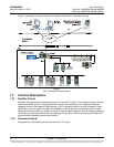
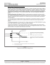
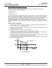
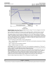
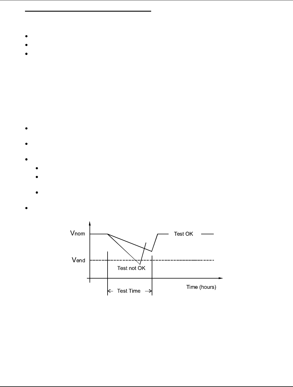
Functional Description: For manual battery discharge tests as well as for cyclic battery discharge tests,
the following parameters must be set: End Voltage, Test Time, and Battery Capacity Discharge Limit. See
Figure 4.
Battery Discharge Test Sequence:
In time test modes, the output voltage of the rectifiers is reduced so that only the batteries power the
load. If the batteries fail, the rectifiers power the load.
In stable current test mode, the output voltage of the rectifiers is reduced so that the batteries supply
the preset test current to the load.
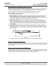
The battery test continues until one of the following occurs:
The preset test time, see Figure 4, expires. The battery has passed the test.
The battery voltage drops below the preset end voltage level (V
end
) (Figure 4). The battery has not
passed the test and the test is interrupted. A battery test alarm is activated.
The battery capacity drops below the preset test end battery capacity. The battery has not passed
the test and the test is interrupted. A battery test alarm is activated.
After the battery discharge test, the output voltage of the rectifiers increase so that the rectifiers supply
the system and charge the batteries.
Figure 4
Battery Test Diagram