


User Instructions UM1M820BNA
Spec No. 1M820BNA (Model M820B) Issue AH, March 4, 2013
Spec No. 1M820DNA (Model M820D)
Chapter 3. Local Display Menus 83
This document is property of Emerson Network Power, Energy Systems, North America, Inc. and contains confidential and proprietary information owned by Emerson Network Power, Energy
Systems, North America, Inc. Any copying, use, or disclosure of it without the written permission of Emerson Network Power, Energy Systems, North America, Inc. is strictly prohibited.
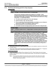
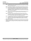
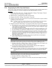
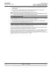
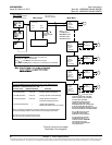
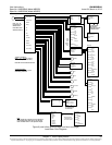
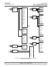
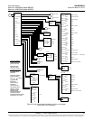
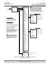
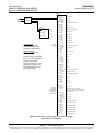
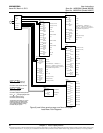
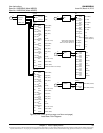
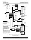
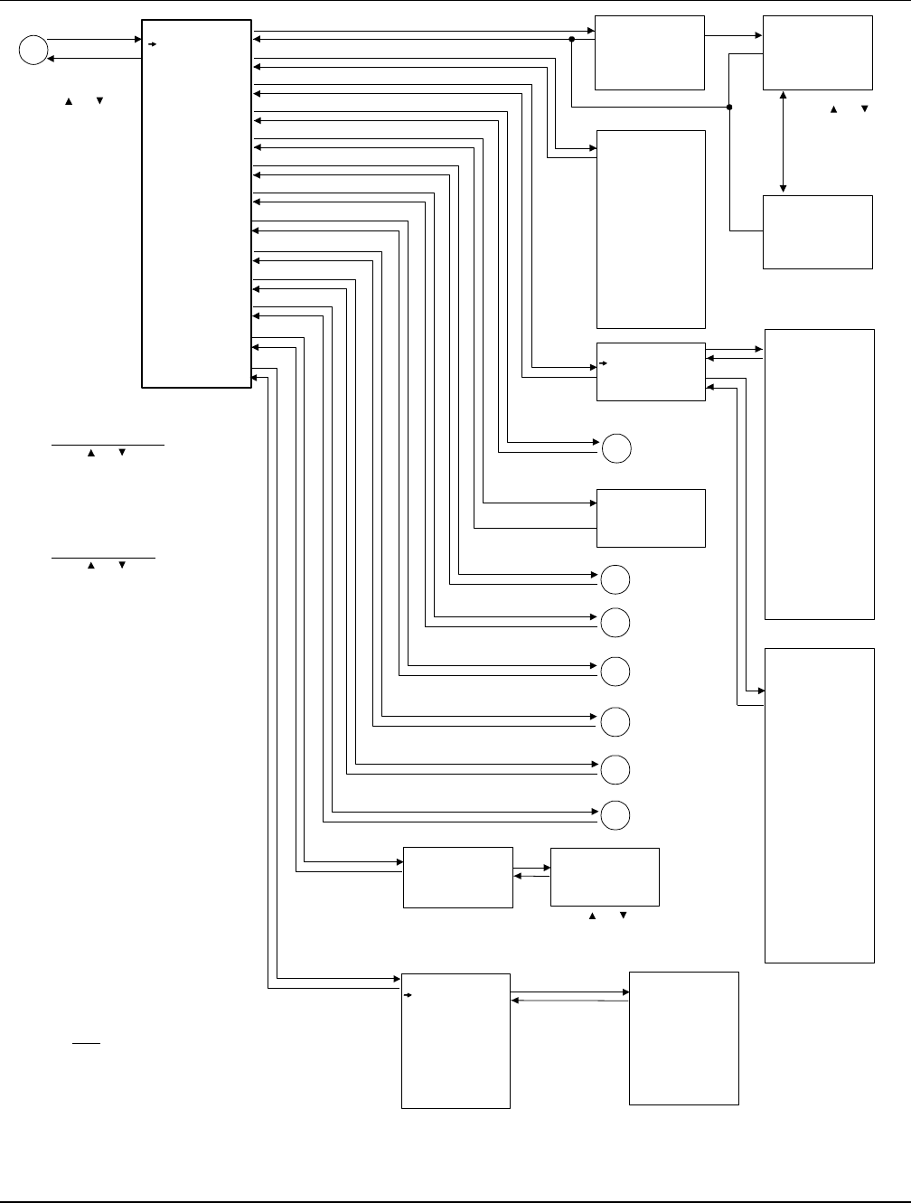
Figure 8 (cont’d from previous page, cont’d on next page)
Local Menu Flow Diagrams
Status
ActiveAlarms
Power System
Rectifier
Battery
DC
AC
EIB
SMDU
Converter
SMDUP
SMTe mp
Alarm History
Sys Inventory
ESC
A
ENT
Active Alarms
Minor: 0
Major: 0
Critical: 2
System Voltage
54.0 V
System Load
0.0A
Mtnc Run Time
1.3 h
Alarm Status
NoAlm
Power Split
Master
IB2 T2
21 deg. C
...
SMTemp1 T1
21 deg. C
DC Voltage
53.8 V
DC Current
8.5A
Temperature
30 deg. C
DC Status
On
AC On/Off
On
Rated Current
35A
Walk-In
Disabled
Rectifier ID
1
Rect Phase
A
Rectifier SN
010700213
Running Time
200 h
AC Voltage
224 V
Rectifier
Rect Group
Rect #1
Rect #2
1 RectAC
Mains Failure
081104 8:00:12
Critical
2 Power System
CAN Comm Fail
081104 8:05:02
Critical
DC Voltage
54.0 V
Load Current
0.0 A
SYS Inventory
ACU+
Rect #1
Rect #2
EIB 1
IB 1
SMDUP 1
Conv #1
Conv #2
SMTemp 1
ENT
ENT
ENT
ENT
ENT
ENT
ESC
ESC
ESC
ESC
ESC
ESC
ESC
ESC
ESC
ENT
ENT
ENT
ESC
ESC
ENT
ENT
ESC
ENT
ESC
ENT
ENT
Press or
to cycle through
list of alarms.
Press ESC to return
to STATUS menu.
Press or
to cycle through
list of alarms.
ENT
ESC
1 IB2
DI3Alarm
100629 12:18:35
100629 12:19:52
Device Name
ACU+
Part Number
M820D
Product Ver
001
SW Version
2.25
Serial Number
21024402512
ENT
ESC
ENT
ESC
Power System
DC
Alarm History
Minor: 0
Major: 0
Critical: 1
Press or
to move cursor in
STATUS screen.
Press ENT to enter
selected sub-menu.
To View Parameters:
Press or to move up and
down list of parameters.
To Select a Sub-Menu:
Press or to move cursor in
menu screen (selects menu item).
Press ENT to enter selected sub-menu.
Note:
For a complete list of alarms that can be displayed
in the STATUS Active Alarm menus, see the table
titled “Available Alarms” in the Operation Chapter.
A3
ESC
A2
A5
A6
Average Voltage
52.0 V
Total Current
0.2A
Number of Rects
2
Num RectsComm
2
SysCap Used
0.9 %
Max Cap Used
3.4 %
Min CapUsed
0.0 %
Rated Voltage
52.0 V
AC Phases
Single Phase
Max Curr Limit
462.2A
Total RatedCur
382.0A
Rect Group
Battery
AC
EIB
ESC
A4
SMDU
Converter
Similar information
is displayed for each
device in the system.
SMDUP
A7
SMTemp
Rect #1
A1
ENT
ESC
Temp.
Probes
set as
“ambient”
show up
here.