


User Instructions UM1M820BNA
Spec No. 1M820BNA (Model M820B) Issue AH, March 4, 2013
Spec No. 1M820DNA (Model M820D)
Chapter 2. Operation 73
This document is property of Emerson Network Power, Energy Systems, North America, Inc. and contains confidential and proprietary information owned by Emerson Network Power, Energy
Systems, North America, Inc. Any copying, use, or disclosure of it without the written permission of Emerson Network Power, Energy Systems, North America, Inc. is strictly prohibited.
2.7 Power Split Feature
In Power Split applications, the output of the power system controlled by the ACU+ can be connected in
parallel with an existing power system. Each system is controlled independently via its own Controller.
The ACU+ power system is referred to as the "slave" system and the existing power system as the
"master" system. The Power Split feature controls the ACU+ power system’s output voltage and rectifiers'
current limit so that the "slave" power system shares the load with the "master" system.
Optional Functions: The ACU+ Controller can mimic the equalize and battery test functions of the “master”
system’s Controller. In addition, the ACU+ Controller can mimic the low voltage load disconnect and/or
low voltage battery disconnect functions of the “master” system. This is accomplished by supplying digital
signals from the “master” system’s Controller to the ACU+. This allows these functions to remain active in
the “master” system.
2.7.1 Overview
See “1.3.7 Power Split Feature”.
2.7.2 How Power Split Works
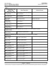
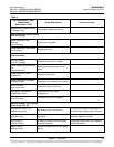
There are four User adjustable parameters for Power Split. They are:
Slave Curr Lmt: Current limit point for power system designated as the slave system in a "Power
Split" configuration.
Delta Volt: The offset voltage that the power system designated as the slave system in a "Power
Split" configuration is set to. It is suggested to leave this value at the default (0.5 volts).
Proportion Coeff: The proportional coefficient that the power system designated as the slave system
in a "Power Split" configuration is set to. It is suggested to leave this value at the default (30%).
Integral Time: The integral time that the power system designated as the slave system in a "Power
Split" configuration is set to. It is suggested to leave this value at the default (60 seconds).
The ACU+ Controller uses these parameters to control the load sharing operation between the two power
systems.
Depending on the systems’ configurations, their rectifier capacities, their distribution load capacities, and
the Power Split configuration; four operating modes can occur.
Low Load Operation
When the total load current demand is lower than the SLAVE CURRENT LIMIT value, the ACU+ power
system voltage will be increased by the programmed DELTA VOLTAGE setting forcing the ACU+ power
system to carry the load. Make sure that the output voltage does not exceed the battery float range
recommended by the manufacturer. In this operating mode, no current will be delivered by the existing
power system.
Normal Load Operation
When the total load current demand reaches the SLAVE CURRENT LIMIT value, the ACU+ power
system operates in output current limit and its output voltage will be decreased (up to the DELTA
VOLTAGE setting) in order to regulate the current, allowing the existing power system to deliver the
remaining current. Both the ACU+ power system and the existing power system are now providing current
to the load.
High Load Operation
If current demand increases and the existing power system reaches its current limit setting, float voltage
will again begin to decrease. When the voltage falls below the float setting minus the DELTA VOLTAGE
setting, the ACU+ system will come out of current limit and now deliver the additional current necessary to
satisfy the load. This operation may occur when the batteries are being recharged, such as after a
commercial AC failure.