


User Instructions UM1M820BNA
Spec No. 1M820BNA (Model M820B) Issue AH, March 4, 2013
Spec No. 1M820DNA (Model M820D)
Chapter 1. Introduction 11
This document is property of Emerson Network Power, Energy Systems, North America, Inc. and contains confidential and proprietary information owned by Emerson Network Power, Energy
Systems, North America, Inc. Any copying, use, or disclosure of it without the written permission of Emerson Network Power, Energy Systems, North America, Inc. is strictly prohibited.
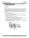
Fixed Daily Time based operation is intended to be used with a combination of AC powered active
cooling (air conditioners) and DC powered cooling (heat exchangers, etc). The cycle period is
synchronized to the 24hr day-night cycle. It makes optimum use of the different temperature conditions
during the day and the night in order to facilitate Hybrid fuel saving operation.
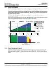
Capacity Discharge based operation is intended for sites utilizing only DC powered cooling (heat
exchangers, etc). The cycle period is determined by User selectable depth of discharge (DOD) of the
batteries per cycle and associated recharge time. It provides optimum Hybrid fuel saving operation.
Operation from Grid Power is performed with both Fixed Daily Time and Capacity Discharge modes of
operation. Grid power is always given priority when available.
As the two types of control are specific to the hardware configuration of the site, the Fixed Daily Time or
Capacity Discharge is a User selectable option on installation.
Hybrid Operation
Generator Control: Potential free relay contact output from the ACU+ interface board controls the start
and stop of the diesel generator. The signal is generated by the ACU+ Controller and operates according
to the Hybrid software mode of operation. The control logic is as follows:
Energized output relay – Generator OFF.
De-energized output relay – Generator ON.
This is a fail-safe logic to ensure generator operation in all cases where power or control to the relay is
lost.
Further to that, the type of signal to the generator can be selected as N/O (Normally Open) or N/C
(Normally Closed) by selecting the relevant output pins of the control relay.
Number of Generator Control Outputs: The ACU+ Hybrid software can control one or two generators.
Each generator control is designated as DG1 or DG2 output. A User selectable menu will allow selecting
DG1, DG2, or DG1 and DG2. When both are selected they will be alternatively used (two generator
operation).
Diesel Fail Alarm: A diesel fail alarm will be generated if the Diesel Generator ON signal fails to bring the
generator to operation and provide the system with AC power. Alarm will be triggered after 60 seconds
(default value, settable) from ON signal. If two generator operations are selected simultaneously with the
alarm, the second Diesel Generator ON signal will be activated.
Battery Fuse Trip Alarm: In the event of a Battery Fuse trip condition an alarm will be generated.
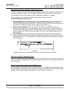
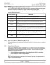
Under Voltage Alarms:
Under Voltage Alarm 1: An Under Voltage Alarm 1 is set. If voltage decreases below this setting, an
alarm is raised.
Under Voltage Alarm 2: An Under Voltage Alarm 2 is set. If voltage decreases below this setting, the
Diesel Generator is started and an alarm is raised.
LVD 1: Normal loads are disconnected.
LVD 2: Priority loads are disconnected.
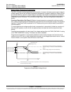
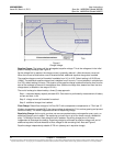
Charge Voltage:
Refer to Figure 6.